Advertisement
Table of Contents
Advertisement
Table of Contents
Troubleshooting

Related Manuals for DAVIS Vantage Pro2


Summary of Contents for DAVIS Vantage Pro2
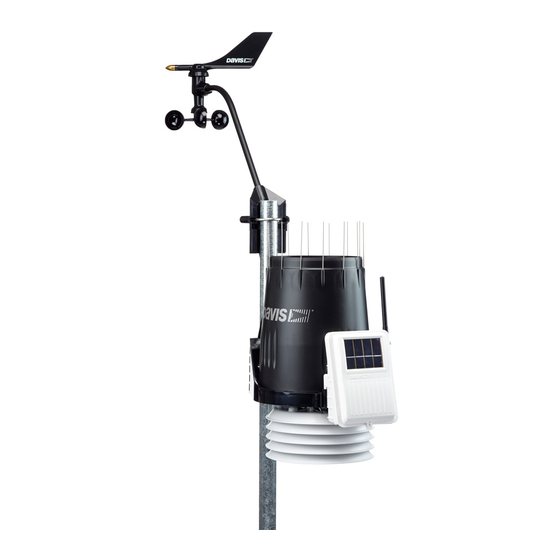
- Page 1 Integrated Sensor Suite Installation Manual ™ ™ For Vantage Pro2 & Vantage Pro2 Plus Weather Stations ® Davis Instruments, 3465 Diablo Avenue, Hayward, CA 94545 USA • 510-732-9229 • www.davisnet.com...
-
Page 2: Table Of Contents
• Consult the dealer or an experienced radio/TV technician for help. Changes or modification not expressly approved in writing by Davis Instruments may void the warranty and void the user's authority to operate this equipment. FCC ID: IR2DWW6328 IC: 378810-6328... -
Page 3: Introduction
Note: If you are using a wireless ISS, it can transmit to a Vantage Pro2 console, as well as a Davis Van- tage Vue console or Davis Weather Envoy. One ISS can transmit to any number of receivers within its range, so you can add additional consoles to use in different rooms. - Page 4 Preparing the ISS for Installation Note: If the ISS is a Plus model and contains UV and solar sensors, do not touch the small white diffusers on top of the sensors. Oil from skin reduces their sensitivity. If you are concerned that you have touched the diffusers at any time during the installation, clean the UV diffuser using ethyl alcohol with a soft cloth.
- Page 5 Preparing the ISS for Installation • Apply power to the ISS and test communication with the console. • Change the Transmitter ID for wireless communication, if necessary. Assemble the Anemometer The anemometer measures wind direction and speed. The anemometer arm comes partially assembled with the wind vane attached.
- Page 6 Check SIM Sensor Connections Attaching the Wind Cups 1. Push the wind cups up onto the anemometer’s stainless steel shaft. 2. Slide the wind cups up the shaft as far as possible. Note: Make sure to push the cups onto the stainless steel shaft as far up the shaft as possible. Failure to do so will cause the anemometer to function improperly.
- Page 7 Check SIM Sensor Connections Open the SIM Box 1. Locate the white box with the solar panel containing the SIM on the front of the ISS unit. The cabled model does not have a solar panel. 2. Locate the white tab at the bottom cen- ter of the SIM box cover.
- Page 8 Check SIM Sensor Connections Connect the Anemometer Cable to the SIM 1. Unwind the coil of cable enough to work with the anemometer. Note: Do not unwind the entire coil of anemometer cable at this time. 2. Pull the foam insert out of cable access port in between the cables and set the foam insert aside.
-
Page 9: Cabled Iss Assembly
The 100' (30 m) console cable provides power to the ISS and is used to send data from the ISS to the console. The console cable can be extended up to 1000' (305 m) in length with extension cables purchased from Davis Instruments. 1. Locate the 100' console cable included with your system. - Page 10 LED indicator light and the DIP switches. Note: If the LED is flashing rapidly, call Technical Support. See “Contacting Davis Instruments” on page 27 for more information. If the console is still not receiving readings, ensure that the console is in Setup Mode and reboot the console by disconnecting the AC power adapter from the console and removing the console batteries for at least 30 seconds.
-
Page 11: Wireless Iss Assembly
Wireless ISS Assembly The ISS has a wireless connection to a Vantage Pro2 wireless console. Once the anemometer has been installed and the sensors have been checked, the ISS must be powered and a wireless communication channel must be established between the ISS and the console. - Page 12 Verifying Data from the ISS Sensors Verifying Data from the ISS Sensors Use these steps to verify reception of ISS data at the wireless Vantage Pro2 console and to test the operation of the ISS sensors. 1. Press and hold DONE until the Current Weather screen displays, if the console is in Setup Mode.
- Page 13 Troubleshooting Wireless ISS Reception Note: If the LED is flashing rapidly, call Technical Support. See “Contacting Davis Instruments” on page 27 for more information. See “SIM Board Display and Contents” on page 29 for information on locating the components and points of interest on the SIM board.
- Page 14 Troubleshooting Wireless ISS Reception DIP Switches Transmitter ID DIP Switches in Top-right Corner of SIM To change to another ID, use a ballpoint pen or paper clip to toggle DIP switches #1, 2, and 3. The settings for Transmitter IDs 1 - 8 are shown in the table below. Set the Vantage Pro2 console to the same ID as the transmitters, as described in the Vantage Pro2 Console Manual.
-
Page 15: Preparing The Iss For Installation
Preparing the ISS for Installation Once all the sensors have been connected and communication between the ISS and the console has been successfully established, continue to prepare the ISS unit for installation. The steps for preparing the ISS for installation are as follows. •... - Page 16 Prepare the Rain Collector 2. Carefully cut and remove the Tipping Bucket plastic tie that holds the tipping bucket in place during shipping (usually yellow or white in color). 3. On your console screen, look for the DAILY RAIN display. If the console is cabled to the ISS, reconnect the cable and see if the console is receiving rain...
- Page 17 Locating the ISS and Anemometer 4. Separate an end cap from one end of the magnet. Separate magnet from one end cap Insert magnet with other end cap into metric measurement adapter 5. Slide the magnet, exposed end of magnet first, into the open slot of the metric adapter.
- Page 18 For roof mounting, and ease of installation, we recommend using the optional mounting tripod (#7716). For other installations, use the Mounting Pole Kit (#7717). Note: For more detailed siting suggestions, see Application Note #30: Reporting Quality Observations to NOAA on the Davis Support web site (http://www.davisnet.com/support/weather).
- Page 19 40' (12 m) cable to go between the ISS and the ane- mometer. This can be extended up to 540' (165 m) using optional extension cables pur- chased from Davis Instru- Anemometer ments. Cable • If most of the anemometer...
- Page 20 Locating the ISS and Anemometer If your ISS is directly overhead, the orientation illustrated here might work best. For best reception, orient antennas so they are parallel to each other. • If possible, align the pivot joints of both the ISS and the console antennas so that they are facing each other for maximum signal strength.
-
Page 21: Installing The Iss
Installing the ISS The anemometer and the main part of the ISS can be installed either together as a single unit on a pole, or apart from each other. The main part of the ISS includes the rain collector, the temperature and humidity sensors, the radiation shield, and the SIM housing. -
Page 22: Installation Instructions
Installing the ISS on a Flat Surface Installation Instructions There are several ways to mount and install the ISS unit. The following are installation types that Davis Instruments recommends. Individual ISS locations and installations may vary. • Installing the ISS on a flat surface •... - Page 23 Installing the ISS on a Pole Option 2: Installing the Anemometer on a Post or Flat Surface 1. With a 3/16" (5 mm) drill bit, drill two holes approximately 2 " (54 mm) apart. Use a carpenter’s level to ensure the holes will be level. 2.
- Page 24 Installing the ISS on a Pole Guidelines for Installing the ISS on a Pole • When mounting the ISS and anemometer together on opposite sides of the pole, remember that whichever side is mounted first, the U-bolt from the opposite side must also be placed around the pole before tightening the U-bolts.
-
Page 25: Finishing The Installation
Finishing the Installation For the wireless ISS, swivel the ISS base so the solar panel is facing south (in the Northern Hemisphere), or north (in the Southern Hemisphere). 3. Tighten the hex nuts using an adjustable wrench or 7/16" wrench. 4. - Page 26 Using Extension Cables: Note: Not all cables are compatible with your Vantage Pro2 system. To be sure they will work, order Davis extension cables from your dealer or directly from Davis Instruments. The anemometer can be extended further than 40' from the ISS by using Davis Instruments extension cables (#7876).
-
Page 27: Maintenance And Troubleshooting
Due to the sensitivity of ultraviolet and solar radiation sensors it is common practice for manufacturers to recommend re-calibration after a period of time. Users demanding high accuracy typically recalibrate their sensors annually. Here at Davis Instruments, we have seen less than 2% drift per year on the readings from these sensors. -
Page 28: Troubleshooting
Try removing and then re-installing the cable to correct the faulty connection. If the sen- sor still functions intermittently contact Technical Support. See “Contacting Davis Instruments” on page 27. - Page 29 Remove the wind cups (loosen the set screw) and clear out any bugs or debris. Turn the shaft the cups rotate on. If it feels gritty or stiff, contact Davis Technical Support. Note: Do not lubricate the shaft or bearings in any way.
-
Page 30: Appendix
License: ......Low power (less than 8 mW), no license required Primary power: ....Solar power – Davis solar charger Backup power: . - Page 31 SIM Board Display and Contents SIM Board Display and Contents SENSOR SENSOR INTERFACE INTERFACE MODULE MODULE TEMP TEMP RAIN RAIN WIND WIND Solar Panel Test DIP Switch Temperature/Humidity Sensor Connector AC Adapter Socke Battery Socket Wind Sensor Connector Rain Sensor Connector Test LED Solar Radiation Sensor Connector Cabled Connection...
- Page 32 For Vantage Pro2 Weather Stations #6322, 6322C, 6323, 6327, 6327C, 6328 For Vantage Pro2 Plus Weather Stations #6152C, 6162C, 6152, 6162, 6153, 6163 Copyright © 2010 Davis Instruments Corp. All rights reserved. Information in this document subject to change without notice.
Need help?
Do you have a question about the Vantage Pro2 and is the answer not in the manual?
Questions and answers