
Related Manuals for DAVIS Vantage Vue ISS


Summary of Contents for DAVIS Vantage Vue ISS
- Page 1 ® Integrated Sensor Suite Installation Manual Model #6357 3465 Diablo Ave., Hayward, CA 94545 USA 510.732.9229 • www.davisnet.com...
-
Page 2: Table Of Contents
Connect the equipment into an outlet on a circuit different from that to which the receiver is connected. • Consult the dealer or an experienced radio/TV technician for help. Changes or modification not expressly approved in writing by Davis Instruments may void the warranty and void the user's authority to operate this equipment. FCC ID: IR2DWW6357... -
Page 3: Introduction
ISS sensors and transmits that data to your Vantage Vue console. Note: Your Vantage Vue ISS can transmit to an unlimited number of consoles, so you can purchase addi- tional consoles to use in different rooms. It can also transmit to Davis Vantage Pro2 consoles and Davis Weather Envoys as well as Vantage Vue consoles. -
Page 4: Hardware
Hardware Hardware included with the Vantage Vue ISS: Battery cover with thumbscrew U-Bolt 3-Volt lithium battery Backing plate Debris screen 1/4” lock washers 0.05” Allen wrench 1/4” hex nuts Note: If any of the hardware components are missing or not included, contact Customer Service toll free at 1-800-678-3669 about receiving replacement hardware or other components. -
Page 5: Attach The Wind Cups To The Anemometer
Attach the Wind Cups to the Anemometer The Vantage Vue anemometer measures wind speed. The wind cups are mounted on the anemometer shaft on the top of the ISS assembly. 1. Gently slide the wind cup assembly down onto the anemometer’s Install cups onto Tighten set screw stainless steel shaft. -
Page 6: Install The Rain Collector Tipping Spoon Assembly
Install the Battery The Vantage Vue ISS SIM board stores energy from the solar panel for power at night. A 3- volt lithium battery provides a backup power source. The battery compartment is located on the underside of the ISS base. -
Page 7: Advanced Installations: Confirm The Transmitter Id
Vue ISS, and an optional anemometer transmitter kit. Note: If you are using only the Vantage Vue console and ISS, and there are no other Davis weather stations nearby, you can skip to “Verify Data from the ISS” on page 6. -
Page 8: Verify Data From The Iss
Note: A good way to ensure that your console is listening to your ISS and not another Davis station nearby, is to make sure the wind values displayed match your wind vane’s direction in reference to the solar panels, which are assumed to be facing south. -
Page 9: Installing The Iss
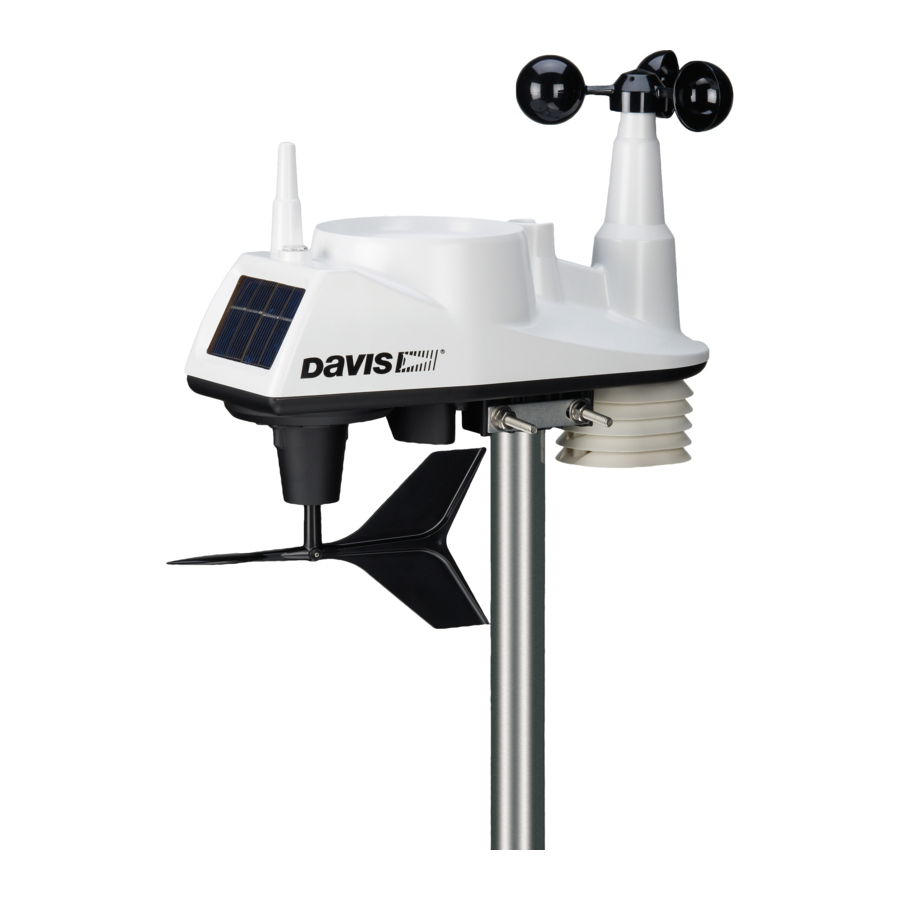
Installing the ISS Choosing a Location for the ISS The ISS assembly includes the rain collector, wind vane, anemometer, temperature and humidity sensors, radiation shield, and SIM housing. You will use the U-bolt and associated nuts and washers that are included with your ISS mounting hardware package to install the ISS on a pole. -
Page 10: Mounting The Iss
The Vantage Vue ISS can only be mounted on the top of a pole or rod. Note: A mounting pole is not included with your Vantage Vue ISS and must be purchased separately, either from Davis Instruments or from your local hardware retailer. - Page 11 Installing the ISS on a Pole 1. If you are mounting your ISS on a Davis Mounting Tripod or the pole included with a Davis Mounting Pole Kit, follow the instructions included with those Davis products for proper installation.
-
Page 12: Finishing The Installation
ISS Installation Guidelines 7. If you are in the Northern Hemisphere, rotate the ISS on the pole so that the solar panel is facing south; if you are in the Southern Hemisphere, rotate the ISS so that the solar panel is facing north. -
Page 13: Maintenance And Troubleshooting
Maintenance and Troubleshooting Maintenance Cleaning the Radiation Shield The outer surface of the radiation shield should be cleaned when there is excessive dirt and build-up on the plates. Use a damp cloth to clean the outer edge of each ring. Note: Spraying down or using water excessively to clean the radiation shield can damage the sensitive sensors or alter the data the ISS is transmitting. -
Page 14: Troubleshooting
Interference has to be strong to prevent the console from receiving a signal while in the same room as the ISS. • There is a problem with the Vantage Vue console. 7. If a problem with receiving the wireless transmission still exists, please contact Technical Support. Note: See “Contacting Davis Instruments” on page 13. - Page 15 Remove the wind cups by loosening the set screw, and clear out any insects or debris which may be interfering with the cup rotation. Turn the shaft the cups rotate on. If it feels gritty or stiff, contact Davis Technical Support.
-
Page 16: Appendix A: Specifications
Appendix A: Specifications See complete specifications for your Vantage Vue station on our website: www.davisnet.com Integrated Sensor Suite (ISS) Specifications Operating Temperature........-40° to +150°F (-40° to +65°C) Non-operating (Storage) Temperature ....-40° to +158°F (-40° to +70°C) Current Draw (ISS SIM only)......0.20 mA (average), 30 mA (peak) at 3.3 Solar Power Panel (ISS SIM) ......
Need help?
Do you have a question about the Vantage Vue ISS and is the answer not in the manual?
Questions and answers