Table of Contents
Advertisement
Quick Links
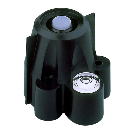
The Davis Solar Radiation Sensor is a precision instrument that detects radia-
tion at wavelengths of 300 to 1100 nanometers. The spectral response of the sil-
icon photodiode detector is a good match to the spectrum of solar irradiance.
Avoid touching the small white diffuser at the top of the sensor. Any skin oil
on this surface will degrade the sensitivity of the sensor. To remove any oil
present, clean the diffuser with a clean swab and ethyl (denatured) alcohol. Do
NOT use rubbing alcohol.
The sensor is made up of the following components:
Shield
The outer shell shields the sensor body from thermal radiation and pro-
vides a path for convection cooling of the body, minimizing heating of
the sensor interior. It provides a cutoff ring for cosine response, a level
indicator, and fins to aid in aligning the sensor with the sun's rays.
Body
The body houses the following components:
Diffuser
Welded to the body for a weather-tight seal. Provides excellent
cosine response.
Detector
An hermetically-sealed silicon photodiode.
Amplifier
The amplifier converts the detector current into a 0 to +2.5V signal.
Cable
The standard version of the sensor includes an attached 40' (12 m)
standard cable. The industrial version includes a 16' (5 m) shielded
cable. The Vantage Pro version comes with a 3' (0.9 m) standard
cable.
S
R
O L A R
S
E N S O R
S
, I
T A N D A R D
V
P
A N T A G E
R O V E R S I O N S
A D I A T I O N
, &
N D U S T R I A L
Product # 7821, 7823, 6450
Advertisement
Table of Contents

Related Manuals for DAVIS Solar Radiation Sensor


Summary of Contents for DAVIS Solar Radiation Sensor
- Page 1 The Davis Solar Radiation Sensor is a precision instrument that detects radia- tion at wavelengths of 300 to 1100 nanometers. The spectral response of the sil- icon photodiode detector is a good match to the spectrum of solar irradiance. Avoid touching the small white diffuser at the top of the sensor. Any skin oil on this surface will degrade the sensitivity of the sensor.
- Page 2 Medium Phillips screwdriver Scissors Center punch or nail (if mounting on wood surface) Drill with 7/8" (22 mm) and #36 (2.7 mm) drill bits (if mounting on wood surface) Wire cutters and stripper (industrial version only) Page 2 EEDED Solar Radiation Sensor...
-
Page 3: Table Of Contents
Testing the Sensor... 12 Accessing the SIM... 12 Securing the Sensor on the Shelf... 13 Routing Sensor Cable... 14 If You Are Going to Install the Solar Radiation Sensor... 15 Maintaining the Sensor... 15 Technical Support... 16 PECIFICATIONS ARE For detailed technical information on the solar radiation sensor, call Technical Support (510) 732-7814 to request a specification sheet, or download it from our... -
Page 4: Installing The Sensor
The Sensor Tilting Bracket #7706 is designed for this purpose. Typical Standard Installation The illustration below shows typical standard solar radiation installation. The sensor cable attaches to connector S5 on the sensor interface module (SIM). Page 4 YPICAL TANDARD NSTALLATION Solar Radiation Sensor... -
Page 5: Typical Industrial Installation
Typical Industrial Installation The illustration below shows typical industrial solar radiation installation. The sensor cable attaches to connector S5 on the sensor interface module (SIM). Standard and Industrial Versions: Installation YPICAL NDUSTRIAL NSTALLATION Page 5... -
Page 6: Mounting On The Sensor Mounting Arm
6. Using the bubble level on the sensor as a guide, adjust the sensor until it is level by tightening or loosening the levelling screws as necessary. Page 6 LACING HIELD ONTO OLAR ADIATION ENSOR ON THE Solar Radiation Sensor... -
Page 7: Mounting On The Sensor Tilting Bracket
7. Secure the sensor cable to the underside of the mounting arm using the 3/16" cable clamp, #8-32 x 3/4" screw, #8 hex nut, and #8 flat washer as shown below. Mounting the Sensor on the Sensor Tilting Bracket Follow the instructions below to mount the sensor on the Sensor Tilting Bracket. - Page 8 If you are installing both the solar radiation and the UV sensor on the sensor tilting bracket, make sure you mount the solar radiation sensor on the sen- sor tilting bracket before attaching to the sensor mounting arm.
- Page 9 8. If necessary, adjust the position of the sensor by tightening or loosening the levelling screws. When pointed directly at the sun, the shadows from the alignment fins should appear as shown in the illustration below. 9. Secure the sensor cable to the underside of the mounting arm using the 3/16" cable clamp, #8-32 x 3/4"...
-
Page 10: Mounting On A Wood Surface
6. Place a spring over the end of each screw and hold the springs in place using a #4 screw retainer. Use the template below to center-punch or mark pilot holes before drilling. OLAR Page 10 LACING HIELD ONTO ADIATION ENSOR OUNTING OLES EMPLATE Solar Radiation Sensor... -
Page 11: Routing Sensor Cable
7. Secure the sensor to the mounting surface by driving the screws into the appropriate holes as shown below. OUNTING THE 8. Using the bubble level on the sensor as a guide, adjust the sensor until it is level by tightening or loosening the levelling screws as necessary. -
Page 12: Vantage Pro Version: Installation On The Sensor Mounting Shelf
ERSION Follow these instructions to mount the solar radiation sensor on the shelf. The shelf has two large holes, to hold a solar radiation sensor and a UV sensor. It doesn’t matter which hole you use first. Testing the Sensor On Vantage Pro’s Integrated Sensor Suite (ISS), the sensor interface module, or... -
Page 13: Securing The Sensor On The Shelf
Securing the Sensor on the Shelf 1. Remove the rain collector cone: turn it counter-clockwise until the latches allow you to lift it up and off. 2. Place the shield onto the body as shown. 3. Route the sensor cable down through one of the large holes in the mounting shelf. -
Page 14: Routing Sensor Cable
Cable Tie #1 rain collector. Cable Tie #2 Page 14 Cable Notch Cable Clamps Cable Tie #3 NOTE: Route sensor cable(s) out through this hole Tipping Bucket Solar Radiation Sensor... -
Page 15: If You Are Going To Install The Solar Radiation Sensor
If you’re installing the UV sensor also, use the same testing and installation procedure just completed for the solar radiation sensor. In the rain collector base, the cable clamps have room to secure one loop of the UV sensor cable and one loop of the solar radiation sensor cable. -
Page 16: Technical Support
Product Numbers: 7821, 7823, 6450 Davis Instruments Part Number: 7395.092 Solar Radiation Sensor, Standard, Industrial & Vantage Pro versions Rev. C Manual (1/12/01) This product complies with the essential protection requirements of the EC EMC Directive 89/336/EC.
Need help?
Do you have a question about the Solar Radiation Sensor and is the answer not in the manual?
Questions and answers