Table of Contents
Advertisement
Quick Links
H-4602, H-4603
π
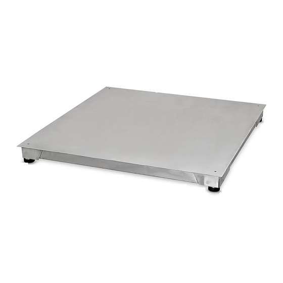
H-4604
stainless steel
low profile
floor scale
Select a site for your new floor scale where it is least
likely to be damaged by forklifts and other material
handling devices. Floor scale load cell weighing
elements are prone to overload damage caused by
side impacts, falling objects and weight loads that
exceed the rated capacity of the scale.
Your site should be:
• Level within 1/4".
• Free from vibration.
• Clean of debris.
• Out of the way of vehicle traffic patterns, unless
installed in a pit while having a rated capacity
that exceeds all loaded vehicle weights that could
possibly drive onto or contact the scale.
The cable from the floor scale to the digital weight
indicator should be run through conduit to protect it
against possible damage. Running the instrument cable
through conduit is the best method of protection.
UnPAcKinG
1. Inspect your shipment for damage. If you see visible
signs of damage, notify your carrier at once.
2. Remove your new floor scale from the shipping
pallet.
3. Unpack the digital indicator. The indicator should
include the digital indicator and power cord.
PAGE 1 OF 6
1-800-295-5510
uline.com
site selection
RAMP instAllAtion (oPtionAl)
Set your new floor scale in a desired location.
Position the scale feet inside the mounting tabs.
(See Figure 1)
Anchor the ramp to the floor using two 1/2" x 3" anchors.
Ramp
Load Cell Foot
HeiGHt And level AdjUstMents
1. Unlock the locknuts on all four feet.
2. Using a pry bar, lift the weight of the scale base off
the scale feet.
3. Make adjustments by screwing the feet
Counterclockwise. All four feet should make firm
contact with the floor.
4. Do not screw feet counterclockwise more than ten
turns.
5. Tighten locknuts on feet.
6. Check your work.
Figure 1
Mounting Tabs
Scale
Anchor goes here
0114 IH-4602
Advertisement
Table of Contents

Related Manuals for U-Line H-4602


Summary of Contents for U-Line H-4602
- Page 1 H-4602, H-4603 π 1-800-295-5510 H-4604 uline.com stainless steel low profile floor scale site selection RAMP instAllAtion (oPtionAl) Select a site for your new floor scale where it is least likely to be damaged by forklifts and other material Set your new floor scale in a desired location.
- Page 2 QtY. Stainless Steel Box Instrument Cable LP7510SS Access Plate Access Plate Screw Load Cell - 5,000 lb. Capacity (H-4602) Load Cell - 10,000 lb. Capacity (H-4603) Load Cell Bolt Stainless Steel Self-Leveling Foot LP7510 Stainless Steel Digital Indicator PAGE 2 OF 6...
- Page 3 AsseMBlY set UP instRUctions 3. Route the cable from the inside of this compartment through the opening in the backside and out from note: Your floor scale was shipped with the four under the scale to your digital weight indicator. threaded leveling feet adjusted for a flat and 4.
- Page 4 disPlAY indicAtoR And fUnction KeYs The display indicator utilizes an LED (Light Emitting lb/kg Diode) display. LEDs are used indoors where brightness ON/OFF Total Count lb/kg Gross Tare Zero Print is needed. The tables below summarize the LED and Key Functions.
- Page 5 oPeRAtion PoWeR on/off note: there are 8 digits total. the display shows the first 4 digits, then the last 4 digits. Press the On/Off key for two seconds to turn the scale for example, when the first 4 digits displayed on or off.
- Page 6 tRoUBlesHootinG PossiBle tARe oPeRAtion codes eRRoR ReAson solUtion UUUUUUUU • Weight overload • Reduce the weight • Bad connection with load cell • Check load cell connection • Load cell has quality problem • I nspect load cell. Check input and output nnnnnnn • Calibration error • Check that scale is level • Bad connection • Check load cell connection • Load cell has quality problem • I nspect load cell. Check input and output MAintenAnce • Protect the display indicator from direct sunlight. • Power off the indicator during electrical storms. • Maintain a good connection between load cell's • Power off the indicator before plugging and instrument cable connector and indicator.
Need help?
Do you have a question about the H-4602 and is the answer not in the manual?
Questions and answers