Table of Contents
Advertisement
Quick Links
Advertisement
Table of Contents

Related Manuals for Pilz PSEN sl-1.0n 2.1


Summary of Contents for Pilz PSEN sl-1.0n 2.1
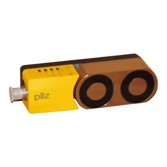
- Page 1 PSEN sl-1.0n 2.1/2.2 PSEN sensor technology Operating Manual-1003806-EN-02...
- Page 2 Preface This document is a translation of the original document. All rights to this documentation are reserved by Pilz GmbH & Co. KG. Copies may be made for internal purposes. Suggestions and comments for improving this documentation will be gratefully received.
-
Page 3: Table Of Contents
Teaching in the actuator PSEN sl-1.0n 2.1 PSEN sl-1.0n 2.2 Installation Note regarding the free-moving actuator PSEN sl-1.0fm Installing on a swing gate Installing on a sliding gate Adjustment Operation Error display through flashing codes Operating Manual PSEN sl-1.0n 2.1/2.2 1003806-EN-02... - Page 4 Contents Dimensions in mm Technical Details Order No. 570604-570605 Technical Details Order No. 570664-570665 Supplementary data Radio approval Safety characteristic data Order reference Safety gate system Accessories EC declaration of conformity Operating Manual PSEN sl-1.0n 2.1/2.2 1003806-EN-02...
-
Page 5: Introduction
PSEN sl-1.0n 2.1/2.2 Introduction Validity of documentation This documentation is valid for the product PSEN sl-1.0n 2.1/2.2. It is valid until new docu- mentation is published. This operating manual explains the function and operation, describes the installation and provides guidelines on how to connect the product. -
Page 6: Safety
The following is deemed improper use in particular: Any component, technical or electrical modification to the product Use of the product outside the areas described in this manual Use of the product outside the technical details (see Technical details [ 23]). Operating Manual PSEN sl-1.0n 2.1/2.2 1003806-EN-02... -
Page 7: Safety Regulations
Have a good knowledge of the generic and specialist standards applicable to the spe- cific application. Warranty and liability All claims to warranty and liability will be rendered invalid if The product was used contrary to the purpose for which it is intended Operating Manual PSEN sl-1.0n 2.1/2.2 1003806-EN-02... -
Page 8: Disposal
Do not remove the connector's protective cap until you are just about to connect the unit. This will prevent potential contamination. Unit features Transponder technology for presence detection Device types Pilz coding type: – PSEN sl-1.0n 2.1: fully coded – PSEN sl-1.0n 2.2: uniquely coded different actuators available (see Order reference [ 30]) –... -
Page 9: Function Description
[ 26], under electrical data). If an open winding or a winding short circuit is detected on a locking magnet that is switched on, safety outputs 12 and 22 switch to a low state. Operating Manual PSEN sl-1.0n 2.1/2.2 1003806-EN-02... -
Page 10: Lateral And Vertical Offset
The power supply must meet the regulations for extra low voltages with protective sep- aration (SELV, PELV). The inputs and outputs of the safety switch must have a protective separation to voltages over 60 VDC. Operating Manual PSEN sl-1.0n 2.1/2.2 1003806-EN-02... -
Page 11: Guidelines For Cable Length
Cable type: LiYY 5x0.25 mm² (79 Ohm/km) from Pilz Max. load per safety output 100 mA 500 mA Cable length 45 m 24 m If cable lengths greater than those stated in the table are required, please contact Pilz. Pin assignment 5-pin M12 male connector Cable colour (Pilz Function Terminal designation cable) -
Page 12: Connection To Evaluation Devices
I2 (FS) Evaluation device FS: Failsafe ST: Standard The safety switch PSEN sl-1.0n 2.1/2.2 can be connected to Pilz evaluation devices, for ex- ample. Suitable Pilz evaluation devices are, for example: PNOZelog for safety gate monitoring PNOZpower for safety gate monitoring... -
Page 13: Connection Example Pnoz S3
The connections to two evaluation devices are shown on the following pages, by way of ex- ample: PNOZ s3 and PNOZmulti Connection example PNOZ s3 PSENslock PNOZ s3 Connection example PNOZmulti PNOZmulti PSENslock green yellow Legend: Input OSSD Input OSSD Signal input Operating Manual PSEN sl-1.0n 2.1/2.2 1003806-EN-02... -
Page 14: Teaching In The Actuator
NOTICE No other actuator may be taught in once this actuator has been taught. Installation The safety gate system can be installed on left or right-hinged swing gates or on sliding gates. Operating Manual PSEN sl-1.0n 2.1/2.2 1003806-EN-02... - Page 15 (e.g. cheese-head or pan head screws) or rivets. Alignment errors of the guard must not adversely affect the safety function of the guard. INFORMATION Mounting brackets are available as accessories [ 30]. Operating Manual PSEN sl-1.0n 2.1/2.2 1003806-EN-02...
-
Page 16: Note Regarding The Free-Moving Actuator Psen Sl-1.0Fm
The actuators enable a warped gate to be closed. A gap may occur on the gate as a result. Make sure that the gap remains small enough to exclude the possibility of reaching into the danger zone. Operating Manual PSEN sl-1.0n 2.1/2.2 1003806-EN-02... -
Page 17: Installing On A Swing Gate
Align the safety switch and mounting bracket with the actuator and tighten the screws. Installing on a sliding gate Align the actuator mounting bracket flush with the sliding gate and tighten the screws. Operating Manual PSEN sl-1.0n 2.1/2.2 1003806-EN-02... - Page 18 (Important: do not tighten the screws) Fix safety switch upright with a screw (a), close gate. Align mounting brackets, press firmly together and tighten screw (b). Remove the safety switch and tighten screw (c). Operating Manual PSEN sl-1.0n 2.1/2.2 1003806-EN-02...
-
Page 19: Adjustment
"Power/Fault" LED lights up red: Error message Flashing codes for fault diagnostics are output to the "Safety Gate" or "Input" LED (see Error display through flashing codes). Remedy: Rectify fault and interrupt power supply. Operating Manual PSEN sl-1.0n 2.1/2.2 1003806-EN-02... -
Page 20: Error Display Through Flashing Codes
Once, for one second each Code for 1st digit 4 times, for one second each Code for 2nd digit Once, for one second each Code for 3rd digit 3 times, short Code for error message repeated Operating Manual PSEN sl-1.0n 2.1/2.2 1003806-EN-02... - Page 21 Check cable length and too high (cable is shorten it, if necessary (see too long) max. cable length) Other flashing codes signal an internal error. Remedy: Change device. Operating Manual PSEN sl-1.0n 2.1/2.2 1003806-EN-02...
-
Page 22: Dimensions In Mm
PSEN sl-1.0n 2.1/2.2 Dimensions in mm M5 (6x) 25,9 M12x1 Fig.: Safety switch and locking magnet 22,5 M5 (2x) 2,5° Fig.: Actuator Operating Manual PSEN sl-1.0n 2.1/2.2 1003806-EN-02... -
Page 23: Technical Details Order No. 570604-570605
Classification in accordance with PDDB PDDB EN 60947-5-3 Pilz coding type fully coded uniquely coded Transponder 570604 570605 Frequency band 122 kHz - 128 kHz 122 kHz - 128 kHz Max. transmitter output 15 mW 15 mW Operating Manual PSEN sl-1.0n 2.1/2.2 1003806-EN-02... - Page 24 Temperature of metal surface at ambient temperature: 25 °C 65 °C 65 °C Ambient temperature In accordance with the standard EN 60068-2-14 EN 60068-2-14 Temperature range -25 - 55 °C -25 - 55 °C Operating Manual PSEN sl-1.0n 2.1/2.2 1003806-EN-02...
- Page 25 Assured operating distance Sao 1 mm 1 mm 7 mm 7 mm Typical operating distance So Assured release distance Sar 15 mm 15 mm Repetition accuracy switching distances 40 % 40 % Typ. Hysteresis 3 mm 3 mm Operating Manual PSEN sl-1.0n 2.1/2.2 1003806-EN-02...
-
Page 26: Technical Details Order No. 570664-570665
Classification in accordance with EN 60947-5-3 PDDB PDDB fully coded uniquely coded Pilz coding type Transponder 570664 570665 Frequency band 122 kHz - 128 kHz 122 kHz - 128 kHz Max. transmitter output 15 mW 15 mW Operating Manual PSEN sl-1.0n 2.1/2.2 1003806-EN-02... - Page 27 Temperature of metal surface at ambient temperature: 25 °C 65 °C 65 °C Ambient temperature In accordance with the standard EN 60068-2-14 EN 60068-2-14 Temperature range -25 - 55 °C -25 - 55 °C Operating Manual PSEN sl-1.0n 2.1/2.2 1003806-EN-02...
- Page 28 Assured operating distance Sao 1 mm 1 mm 7 mm 7 mm Typical operating distance So Assured release distance Sar 15 mm 15 mm Repetition accuracy switching distances 40 % 40 % Typ. Hysteresis 3 mm 3 mm Operating Manual PSEN sl-1.0n 2.1/2.2 1003806-EN-02...
-
Page 29: Supplementary Data
2) this product must accept any interference received, including interference that may cause undesired operation. Changes or modifications made to this product not expressly approved by Pilz may void the FCC authorization to operate this equipment. NOTE: This equipment has been tested and found to comply with the limits for a Class A digital device, pursuant to Part 15 of the FCC Rules. -
Page 30: Safety Characteristic Data
Order reference Safety gate system Product type Features Connection type Order No. PSEN sl-1.0n 2.1 / PSEN sl-1.0 Safety gate system, fully M12, 5-pin connector 570 604 coded PSEN sl-1.0n 2.2 / PSEN sl-1.0 Safety gate system, M12, 5-pin connector... -
Page 31: Accessories
European Parliament and of the Council. The complete EC Declaration of Conformity is available on the Internet at www.pilz.com/downloads. Representative: Norbert Fröhlich, Pilz GmbH & Co. KG, Felix-Wankel-Str. 2, 73760 Ost- fildern, Germany Operating Manual PSEN sl-1.0n 2.1/2.2...
Need help?
Do you have a question about the PSEN sl-1.0n 2.1 and is the answer not in the manual?
Questions and answers