Table of Contents
Advertisement
Quick Links
Advertisement
Table of Contents

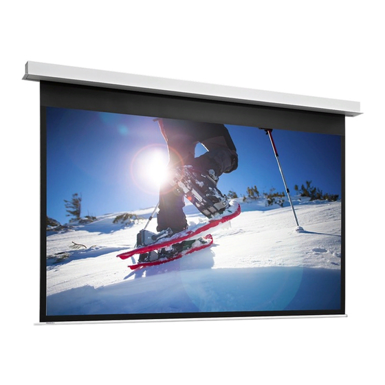
Summary of Contents for Da-Lite DescenderPro
- Page 1 INSTRUCTION BOOK FOR DescenderPro...
-
Page 2: Important Safety Instructions
Milestone makes no representation of warranty, expressed or implied, regarding the information contained herein. Milestone assumes no responsibility for accuracy, completeness or sufficiency of the information contained in this document. Da-Lite® is a registered trademark of Milestone AV Technologies. All rights reserved. Important Safety Instructions When using your video equipment, basic safety precautions 10. - Page 3 Suggested Methods of Installation Method 1 15½" [39.4cm] Fixed Variable Position Bracket Mounting Bracket Audience Side 15½" [39.4cm] Motor 9¼" [23.5 cm] 3/8" Threaded Rod Electrical (Not Included) Junction Box Attached to Mounting Bracket 5¾" [14.6cm] 5" [12.6cm] 5¾" [14.6cm] 2"...
-
Page 4: Tools Required For Installation
Tools Required for Installation 1/2“ Open Wrench 1/8” Hex Key #2 Phillips Screwdriver or Socket Driver (included) Pre-Installation 1. Carefully unpack case from shipping carton. 4. Remove any protective foam covering the outside of the case. 2. Set aside the Installation Kit. Items inside will be used during installation. - Page 5 Case Installation (continued) Test installation by running screen up and down a few times. Install access door. Slide motor end of door onto mounting Be prepared to stop screen should any objects obstruct the post (Figure 5). Lift up slat on pin end side and hook door movement of the screen.
- Page 6 Installation for 120V Screens 120V Wiring Diagram IMPORTANT NOTE: The wall switch is REQUIRED to make any limit switch adjustments, EVEN if a third party control system is 3-conductor 20–24 gauge wire can be used in place of the S T O used.
- Page 7 Installation for 230V Screens 230V Wiring Diagram with Operation & Limit Adjustment IMPORTANT NOTE: The wall switch is REQUIRED to make any Wall Switch limit switch adjustments, EVEN if a third party control system is S T O used. Therefore, it is advised to wire the switch or provide a 3-conductor 20–24 gauge wire can be used in place of the 3-conductor connection that is accessible.
- Page 8 Installation for 230V Screens (continued) 230V Wiring Diagram with European Style Wall Switch IMPORTANT NOTE: The European style wall switch is for operation only and CANNOT be used to make limit switch Use 3-conductor 20–24 gauge wire for wall switch connections. adjustments.
-
Page 9: Screen Adjustment
Screen Adjustment Locate the wall switch and remove the cover plate from the Press and hold the up button until the desired up position is reached. If you travel too far up, press the down button to wall switch and remove the switch from the junction box. move the screen downward. -
Page 10: Operation Of Screen
Operation of Screen Operation & Limit Adjustment Wall Switch “Up” Button Press ”DOWN” button on screen switch and screen will deploy out of case in downward direction. “Stop” Button 2. Press “STOP “button on screen switch and screen will stop if in movement. -
Page 11: Troubleshooting
Conditions for Transportation and Storage • Temperature: Between 40 - 1000F (5 - 400C) • Make sure the entire package is supported when stored • Relative Humidity: 30% to 70%, non-condensing • Do not stack more than six projection screens on top of each other •... - Page 12 Da-Lite’s sole obligation under this warranty shall be to repair or to replace (at Da-Lite’s option) the defective part of the merchandise. Returns for service should be made to your Da-Lite dealer. If it is necessary for the dealer to return the screen or part to Da-Lite, transportation expenses to and from Da-Lite are payable by the purchaser and Da-Lite is not responsible for damage in shipment.


Need help?
Do you have a question about the DescenderPro and is the answer not in the manual?
Questions and answers