
Related Manuals for Xylem G&L A-C 8100 Series


Summary of Contents for Xylem G&L A-C 8100 Series
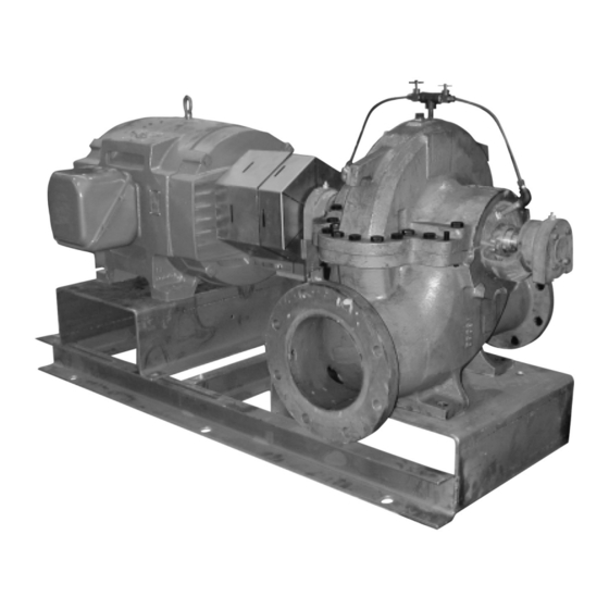
- Page 1 INSTRUCTION MANUAL AC5659D G&L Pumps Series A-C 8100 Base Mounted Centrifugal Pump...
-
Page 3: Table Of Contents
Table of Contents Table of Contents 1 Introduction and Safety......................3 1.1 Introduction.......................... 3 1.2 Safety............................. 3 1.2.1 Safety terminology and symbols.................3 1.2.2 Safety instruction decals....................4 1.3 User safety..........................5 1.3.1 Wash the skin and eyes....................6 1.4 Protecting the environment....................6 2 Transportation and Storage...................... - Page 4 Table of Contents 6 Maintenance..........................28 6.1 Maintenance schedule...................... 28 6.2 Flood-damaged pumps....................29 6.3 Bearing maintenance......................29 6.3.1 Regrease the grease-lubricated bearings............... 29 6.3.2 Lubricating grease requirements................30 6.4 Shaft-seal maintenance..................... 30 6.4.1 Mechanical seal maintenance................... 30 6.4.2 Packed stuffing box maintenance................31 6.5 Cleaning without dismantling the pump................
-
Page 5: Introduction And Safety
This includes any modification to the equipment or use of parts not provided by Xylem. If there is a question regarding the intended use of the equipment, please contact a Xylem representative before proceeding. -
Page 6: Safety Instruction Decals
1 Introduction and Safety Hazard level Indication A hazardous situation which, if not avoided, could result WARNING: in death or serious injury A hazardous situation which, if not avoided, could result CAUTION: in minor or moderate injury Notices are used when there is a risk of equipment NOTICE: damage or decreased performance, but not personal injury. -
Page 7: User Safety
1 Introduction and Safety DO NOT RUN PUMP DRY, SEAL DAMAGE MAY OCCUR. INSPECT PUMP SEAL REGULARLY FOR LEAKS, REPLACE AS REQUIRED. LUBRICATION REQUIREMENTS CONSULT MANUALS. PUMP: POLYUREA-BASED GREASE FAILURE TO FOLLOW INSTRUCTIONS COULD RESULT IN INJURY OR PROPERTY DAMAGE. P2002458 Make sure that all safety instruction decals are always clearly visible and readable. -
Page 8: Wash The Skin And Eyes
• Clean-up of spills Exceptional sites CAUTION: Radiation Hazard Do NOT send the product to Xylem if it has been exposed to nuclear radiation, unless Xylem has been informed and appropriate actions have been agreed upon. Recycling guidelines Always follow local laws and regulations regarding recycling. -
Page 9: Transportation And Storage
2 Transportation and Storage 2 Transportation and Storage 2.1 Examine the delivery 2.1.1 Examine the package 1. Examine the package for damaged or missing items upon delivery. 2. Record any damaged or missing items on the receipt and freight bill. 3. - Page 10 2 Transportation and Storage • Pump end only (bare pump) • Pump less motor • Pump, motor, & baseplate Use the following recommended ways of handling HSC pump assemblies. • The pump assembly should remain horizontal during transport and lifting. •...
- Page 11 2 Transportation and Storage Figure 2: Lift using a forklift 30° MAX. Figure 3: Vertical - Half Pedestal - Model 200 • Place nylon sling, chain or wire rope around both flanges. Use a latch hook or standard shackle and end loops. Be sure the lifting equipment is of sufficient length to keep the lift angle less than 30°...
-
Page 12: Storage Requirements
2 Transportation and Storage NOTICE: Protect the product against humidity, heat sources, and mechanical damage. NOTICE: Do not place heavy weights on the packed product. 2.3 Storage requirements If the unit will not be installed and put into operation immediately upon arrival at the site, or for an extended shutdown after the unit is in operation, the following requirements for short-term storage apply: •... -
Page 13: Product Description
3 Product Description 3 Product Description 3.1 General description Description The pump is a centrifugal, frame-mounted pump. The following pump features make it easy to install, operate, and service: • High efficiency • Rugged construction • Compact design • Foot-mounted volute •... -
Page 14: Nameplate Information
3 Product Description Mechanical seal specifications Seal type Parameter Value Standard self-flushing pH range limits for BUNA pH 7–9 Liquid temperature range that -20˚F to 225˚F (-29˚C to 107˚C) complies with the pH range limits for BUNA pH range limits for EPT pH 7–11 Liquid temperature range that -20˚F to 250˚F (-29˚C to 121˚C) -
Page 15: Installation
(See the nameplate on the drive unit to select properly-sized overloads.) NOTICE: Supervision by an authorized Xylem representative is recommended to ensure proper installation. Failure to do so may result in equipment damage or decreased performance. Evaluate the installation in order to determine that the Net Positive Suction Head Available... -
Page 16: Typical Installation
4 Installation Guideline Explanation/comment Take into consideration the occurrence of unwanted noise The best pump location for noise and vibration and vibration. absorption is on a concrete floor with subsoil underneath. If the pump location is overhead, undertake special Consider a consultation with a noise specialist. precautions to reduce possible noise transmission. -
Page 17: Level The Base On A Concrete Foundation
4 Installation Diagram • An optional 4–inch long tube around the bolts at the top of the concrete allows some flexibility in bolt alignment to match the holes in the baseplate. • Allow enough bolt length for grout, shims, lower baseplate flange, nuts, and washers. 1. -
Page 18: Grout The Baseplate
4 Installation 5. Check to make sure that the piping can be aligned to the pump flanges without placing pipe strain on either flange. 6. Grout the baseplate. See “Grout the baseplate.” 4.1.5 Grout the baseplate Required equipment: • Cleaners: Do not use an oil-based cleaner because the grout will not bond to it. See the instructions provided by the grout manufacturer. -
Page 19: Align The Pump Using A Straight Edge And Calipers
4 Installation Make sure the shaft extends into the hubs at least 0.8 times the diameter of the shaft. 6. Lightly fasten the hubs to the shafts in order to prevent them from moving during alignment. 7. Align the hubs to the values shown in Maximum allowable misalignment for couplings. You can perform alignment with lasers, dial indicators, or with a straight edge and calipers. -
Page 20: Align The Pump Using A Dial Indicator
4 Installation In the following Figure, the arrows show the angular misalignment: Figure 6: Check the alignment using calipers 4.2.3 Align the pump using a dial indicator • Make sure that each hub is secured to its respective shaft and that all connecting and/or spacing elements are removed at this time. -
Page 21: Final Alignment
4 Installation Resilient separator Figure 7: Pump alignment via dial indicator d) Set the dial to zero. e) Rotate both coupling halves together and make sure that the index lines remain matched. f) Reposition the equipment until the offset is within the permissible value. 2. -
Page 22: Coupler Limitations
4 Installation 4.2.7 Coupler limitations Brand Suitable for Minimum Allowable installation misalignment limits Y Dimension Maximum Minimum variable speed recommended (inch) temperature temperature Coupler size Parallel (inch) Angular (inch application speed or degree) 0.010 0.035 1.188 0.010 0.043 1.500 0.015 0.056 1.938 0.015... -
Page 23: Suction Piping Checklist
4 Installation Check Explanation/Comment Always run piping to the pump. Do not move pump to pipe. This could make final alignment impossible. Check that the suction and discharge piping are This helps to avoid strain on the pump when the flange supported independently near the pump and properly bolts are tightened. - Page 24 4 Installation Check Explanation/comment Checked (Optional) You can install a short section of This facilitates the cleansing of the liquid passage of pipe adjacent to the suction flange such as the pump without dismantling the pump. With this Dutchman or a spool piece that is designed arrangement, anything that clogs the impeller is so that it can be readily dropped out of the accessible with the removal of the spool piece or pipe...
- Page 25 4 Installation 1. Air pocket Figure 11: Suction pipe installed with a reducer – incorrect 1. Air pocket Figure 12: Incorrect 1. No air pockets 2. Gradual rise Figure 13: Correct 1. No air pockets 2. Eccentric reducer 3. Gradual rise Figure 14: Gradual rise to the pump –...
-
Page 26: Commissioning, Startup, Operation, And Shutdown
5 Commissioning, Startup, Operation, and Shutdown 5 Commissioning, Startup, Operation, and Shutdown 5.1 Preparation for startup WARNING: • Failure to follow these precautions before you start the unit will lead to serious personal injury and equipment failure. • Do not operate the pump below the minimum rated flows or with the suction or discharge valves closed. -
Page 27: Priming
5 Commissioning, Startup, Operation, and Shutdown 9. Assure that pump is full of liquid (see priming) and all valves are properly set and operational, with the discharge valve closed, and the suction valve open. 10.Check rotation. Be sure that the driver operates in the direction indicated by the arrow on the pump casing as serious damage can result if the pump is operated with incorrect rotation. -
Page 28: Freezing Protection
5 Commissioning, Startup, Operation, and Shutdown 5.1.6 Freezing protection NOTICE: Do not expose an idle pump to freezing conditions. Drain all liquid that is inside the pump and connected pipes. Failure to do so can cause liquid to freeze and damage the pump. Pumps that are shut down during freezing conditions should be protected by one of the following methods: •... - Page 29 5 Commissioning, Startup, Operation, and Shutdown Figure 18: Main joint bolts G&L Pumps Series A-C 8100 Base Mounted Centrifugal Pump INSTRUCTION MANUAL...
-
Page 30: Maintenance
6 Maintenance 6 Maintenance 6.1 Maintenance schedule CAUTION: Shorten the inspection intervals if the pumped liquid is abrasive or corrosive, or if the environment is classified as potentially explosive. NOTICE: This timetable assumes that the unit has been constantly monitored after startup. Adjust the timetable for any extreme or unusual applications or conditions. -
Page 31: Flood-Damaged Pumps
6 Maintenance figures of the last test. This is especially important where the pumped liquid tends to form a deposit on internal surfaces. • Inspect foot valves and check valves. A faulty foot or check valve will cause poor performance. The check valve safeguards against water hammer when the pump stops. -
Page 32: Lubricating Grease Requirements
6 Maintenance 3. Fill both of the grease cavities through the fittings with the recommended grease. Stop when grease leaks out at shaft. 4. If needed, stop pump and wipe off excess grease. 5. Restart pump. The bearing temperature usually rises after you regrease due to an excess supply of grease. -
Page 33: Packed Stuffing Box Maintenance
6 Maintenance 6.4.2 Packed stuffing box maintenance Check or instruction Explanation/comment When starting a pump with fiber packing for Never draw the gland to the point where the packing is compressed the first time, make sure that the packing is too tightly and no leakage occurs. -
Page 34: Drain The Pump
6 Maintenance NOTICE: Make sure that all replacement parts are available before you disassemble the pump for overhaul. 6.6.2 Drain the pump CAUTION: • Allow all system and pump components to cool before you handle them to prevent physical injury. 1. -
Page 35: Disassemble The Pump With Mechanical Seal On The Shaft
6 Maintenance 1. Outer guard 2. Inner guard 3. Attach the support bracket inline with the bolt 4. Support bracket 5. Nut 6. Lockwasher 7. Capscrew 8. Flat washer 9. Spacer washer 10.Option used instead of the spacer where overall guard length exceeds 12 in. (30 cm) or the guard width is over 10 in. -
Page 36: Disassemble The Pump With Mechanical Seals On Shaft Sleeve
6 Maintenance 11.Remove the two casing rings (3–003–9) from the impeller (4–002–0) and remove o-ring (3–914–9) and locating pin (3–943–9) from each casing ring. 12.Remove the mechanical seal head (3–402–0) from the pump shaft. 13.Remove the impeller retaining ring (3–915–1) with retaining ring pliers. Heat the impeller hub on both ends to 350°F maximum, and pull or push the impeller from the shaft. - Page 37 6 Maintenance 7. Remove the snap ring (3–915–4) (or locknut and lockwasher on pumps built after 1991) from the outboard end of the shaft and, using a puller, remove the bearing (3–026–4) from the shaft. Remove the drive end bearing in the same manner. Snap ring is not used on drive end bearings.
-
Page 38: Disassemble The Pump With Packing
6 Maintenance 16.Remove the impeller key (3–911–1). 6.6.6 Disassemble the pump with packing 1. Close valves on suction and discharge sides of pump. If valves have been installed, it will be necessary to drain the system. 2. Remove the coupling guard and disconnect coupling. Refer to instructions on how to remove the hex coupling guard. -
Page 39: Pre-Assembly Inspections
6 Maintenance 10.Remove the two gland bolts, gland halves and packing from each stuffing box. 11.Remove two casing rings (3–003–9) from the impeller (4–002–0) and remove o-ring (3– 914–2) and locating pin (3–943–9) from each casing ring. 12.Loosen set screw (3–902–3) in shaft nut (3–015–9) and remove the nut. On pumps built after 1991, remove o-rings from counterbore in shaft sleeves. -
Page 40: Shaft And Sleeve Inspection
6 Maintenance 6.7.2 Shaft and sleeve inspection Inspection criteria Inspect the shaft and sleeve according to this criteria: • Thoroughly clean the shaft and sleeve. • Thoroughly clean the coverplate seal cavity. • Inspect the surface for damage such as pitting, corrosion, nicks, and scratches. Replace these parts if they are damaged. - Page 41 6 Maintenance Pump with mechanical seals on the shaft sleeves Figure 24: Cross section Setting Dimensions Type 1 Type 21 Type 1B Impeller locating Mechanical seal Mechanical seal Mechanical seal Pump size dimension “A” “B” “A” “B” “A” “B” “C” 3x2x11 6.62 6.75...
- Page 42 6 Maintenance Figure 25: Impeller wear ring Figure 26: Balanced mechanical seal on sleeve — optional extra Figure 27: Dowel pin location at parting line Figure 28: Cross section Pump size Dimension “A” Packing size 3x2x11 8.755 6x4x9 9.312 6x4x10A 9.312 6x4x10 10.625...
-
Page 43: Reassembly
6 Maintenance Pump size Dimension “A” Packing size 8x6x12M 8x6x13 8x6x17 10.625 8x6x18 8x8x12 8x8x17 10x8x12 11.495 10x8x17 10x8x20 11.62 10x10x12 12.995 12x10x12 12x10x14 11.495 12x10x17 Figure 30: Dowel pin location at parting line Figure 29: Impeller wear ring Figure 31: Optional — internal piping with seal cage 6.9 Reassembly 6.9.1 Reassemble the pump with mechanical seal on the shaft All bearings, O-rings, seals, and gaskets should be replaced with new parts during... - Page 44 6 Maintenance Impeller may be pressed onto the shaft if a suitable press is available. 4. Lubricate and roll an O-ring (3–914–2) on each casing ring (3–003–9) and slide the casing rings onto the impeller. 5. Thoroughly clean the stuffing boxes (3–073–9) to prevent dirt from entering the seal during start-up.
- Page 45 6 Maintenance 14.Install the snap ring (3–915–4) (or locknut and lockwasher) on the outboard end of the shaft. 15.Cool the bearing to room temperature and coat both sides with two or three oz of recommended grease. 16.Coat the inside of the bearing housing (3–025–4) with grease and slide into place over bearing.
-
Page 46: Reassemble The Pump With The Mechanical Seals On The Shaft Sleeve
6 Maintenance 23.Rotate the shaft by hand to assure that it turns smoothly and is free from rubbing or binding. 24.Install the coupling and align. Replace the coupling guard. Refer to Install the hex coupling guard instructions. 6.9.2 Reassemble the pump with the mechanical seals on the shaft sleeve All bearings, O-rings, seals, and gaskets should be replaced with new parts during assembly. - Page 47 6 Maintenance 9. Obtain the set collar (3–421–9) locating dimension from the table and scribe the dimension on the shaft sleeves. Install set collar on sleeve per dimension. IMPORTANT: Steps 12 through 16 must be completed within 10–12 minutes to assure proper placement of the mechanical seal.
-
Page 48: Reassemble The Pump With Packing
6 Maintenance 20.Install a new 1/64 in thick gasket with a light coat of commercial cup grease on both gasket surfaces. IMPORTANT: Align the inner edge of the gasket with the stuffing box O-rings. 21.Lower the upper half casing (2–001–7) into place and install casing joint bolts (2–904–1 and –2). - Page 49 6 Maintenance 1. Assemble the impeller key (3–911–1) in the shaft key slot. 2. Check the impeller (4–002–0) and casing to determine the correct impeller rotation and locate the impeller on the shaft per dimension “A” given in table. NOTE: For impellers with replaceable rings, heat each new ring (4–004–9) and slide it onto the impeller.
- Page 50 6 Maintenance 14.Install the locknut and lockwasher or snap ring (3–915–4) on the outboard end of the shaft. 15.Cool the bearing to room temperature and coat both sides with 2 or 3 oz of recommended grease. 16.Coat the inside of the bearing housing (3–025–4) with grease and slide into place over bearing.
-
Page 51: Install The Hex Coupling Guard
6 Maintenance 23.Rotate the shaft by hand to assure that it turns smoothly and is free from rubbing or binding. 24.Install the coupling and align. Replace the coupling guard. Refer to Install the hex coupling guard instructions. 25.Install 12 full rings of packing (6 per stuffing box) so that the ends butt, leaving no gap between the packing and the stuffing box. -
Page 52: Assembly References
6 Maintenance 6.9.5 Assembly references 6.9.5.1 Ordering parts The pumps covered by this manual have been designed and built with certain replaceable wearing parts. The recommended inventory of spare parts depends upon the installation and the importance of continued operation. For critical service requiring a minimum of “down time”... -
Page 53: Troubleshooting
7 Troubleshooting 7 Troubleshooting 7.1 Operation troubleshooting Between regular maintenance inspections, be alert for signs of motor or pump trouble. Correct any trouble immediately and avoid costly repair and shutdown. Symptom Cause Remedy Lack of prime Fill pump and suction pipe completely with liquid. - Page 54 7 Troubleshooting Symptom Cause Remedy Air leaks in suction piping If liquid pumped is water or other non-explosive, and explosive gas or dust is not present, test flanges for leakage with flame or match, or by plugging inlet and putting line under pressure.
- Page 55 7 Troubleshooting Symptom Cause Remedy Mechanical defects See “Defective impeller” and “Foot valve too small or partially obstructed”. Obstruction in liquid passages. Dismantle pump and inspect passages of impeller and casing. Remove obstruction. Air or gases in liquid. (Test in May be possible to over rate pump to laboratory, reducing pressure on point where it will provide adequate...
- Page 56 7 Troubleshooting Symptom Cause Remedy Suction inlet not immersed enough. If inlet cannot be lowered, or if eddies through which air is sucked persist when it is lowered, chain a board to suction pipe. It will be drawn into eddies, smothering the vortex. Liquid heavier (in either viscosity or Use larger driver.
-
Page 57: Product Warranty
8 Product warranty 8 Product warranty Commercial warranty Warranty. For goods sold to commercial buyers, Seller warrants the goods sold to Buyer hereunder (with the exception of membranes, seals, gaskets, elastomer materials, coatings and other "wear parts" or consumables all of which are not warranted except as otherwise provided in the quotation or sales form) will be (i) be built in accordance with the specifications referred to in the quotation or sales form, if such specifications are expressly made a part of this Agreement, and (ii) free from defects in material and... - Page 58 8 Product warranty Limited consumer warranty Warranty. For goods sold for personal, family or household purposes, Seller warrants the goods purchased hereunder (with the exception of membranes, seals, gaskets, elastomer materials, coatings and other "wear parts" or consumables all of which are not warranted except as otherwise provided in the quotation or sales form) will be free from defects in material and workmanship for a period of one (1) year from the date of installation or eighteen (18) months from the product date code, whichever shall occur first, unless a...
- Page 59 8 Product warranty To make a warranty claim, check first with the dealer from whom you purchased the product or visit www.xyleminc.com for the name and location of the nearest dealer providing warranty service. G&L Pumps Series A-C 8100 Base Mounted Centrifugal Pump INSTRUCTION MANUAL...
- Page 60 For more information on how Xylem can help you, go to www.xylem.com Xylem Inc. Visit our Web site for the latest version of this document...
Need help?
Do you have a question about the G&L A-C 8100 Series and is the answer not in the manual?
Questions and answers