
Related Manuals for Xylem GOULDS AC8743


Summary of Contents for Xylem GOULDS AC8743
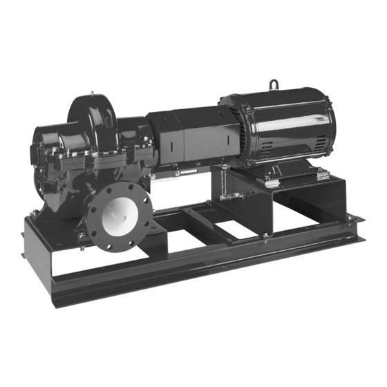
- Page 1 INSTRUCTION MANUAL AC8743 INSTALLER: PLEASE LEAVE THIS MANUAL FOR THE OWNER'S USE. AC 8300 Series BASE MOUNTED CENTRIFUGAL PUMP INSTALLATION, OPERATION AND MAINTENANCE INSTRUCTIONS...
-
Page 4: Safety Instruction
SAFETY INSTRUCTIONS Your Series 8300 pump should have the safety SAFETY INSTRUCTION instruction decals in Figure 2 displayed. If the This safety alert symbol will be used in decals are missing or illegible, contact your local this manual and on the pump safety instruction A-C Pump representative for a replacement. -
Page 5: Additional Safety Instructions
Mechanical Safety ADDITIONAL SAFETY INSTRUCTIONS WARNING: Unexpected Startup Hazard 1. Electrical connections to be made by qualified electrician in accordance with all Disconnect and lockout power before servicing. national, state, and local codes. Failure to follow these instructions could result in 2. - Page 6 If lifting of the entire pump is required, do so with slings placed under the base rails as shown in Figure 3. The best pump location for sound and vibration absorption is on a concrete floor with subsoil underneath. If the pump location is overhead, special precautions should be undertaken to reduce possible sound transmission.
-
Page 7: General Instructions
GENERAL INSTRUCTIONS PURPOSE OF THE MANUAL LOCATION This manual is furnished to acquaint you with The pump should be installed as near the suction some of the practical ways to install, operate, and supply as possible, but no less than five suction maintain this pump. -
Page 8: Base Plate Setting (Before Piping)
Figure 5: Setting Base Plate and Grouting foundation having a mass ≥ 1.5 times the weight of the unit. a. Use blocks and shims under base for support at anchor bolts and midway foundation should poured without between bolts, position base interruption to within 1/2 to 1-1/2 inches of the approximately 1 inch above the concrete... -
Page 9: Alignment Procedure
e. Check the alignment after the foundation ANSI/OSHA COUPLER GUARD bolts are tightened. REMOVAL/INSTALLATION WARNING: Unexpected Startup Hazard Approximately 14 days after the grout has been poured or when the grout has Disconnect and lockout power before servicing. thoroughly dried, apply an oil base paint to the exposed edges of the grout to prevent Failure to follow these instructions could result in air and moisture from coming in contact... - Page 10 guard, and install, but do not tighten, bracket, the inner guard will have to be the two remaining capscrews. positioned so there is only a 1/4 inch of the pump shaft exposed. Position the outer guard so it is centered around the shaft, and so there is less than g.
-
Page 12: Suction And Discharge Piping
T.I.R., while satisfactory angular SUCTION AND DISCHARGE PIPING misalignment is .004" T.I.R. per inch of When installing the pump piping, be sure to radius R. See Figure 8. observe the following precautions: Piping should always be run to the pump. Final Alignment Final alignment cannot be accomplished until Do not move pump to pipe. - Page 13 Friction losses caused by undersized suction CHECK VALVE piping can increase the fluid’s velocity into the GATE VALVE SUCTION PIPE INSTALLED WITH INCREASER pump. As recommended by the Hydraulic A GRADUAL RISE TO PUMP Institute, Standard ANSI/HI 1.1-1.5-1994, suction pipe velocity should not exceed the C OF PIPE velocity in the pump suction nozzle.
- Page 14 When operating on a suction lift, the suction pipe to isolate the pump for maintenance should slope upward to the pump nozzle. A purposes, and should always be installed horizontal suction line must have a gradual rise to in positions to avoid air pockets. the pump.
-
Page 15: Pre-Start Checks
OPERATION CAUTION: Seal Damage Hazard PRE-START CHECKS Before initial start of the pump, make the following Do not run pump dry. Seal damage may occur. inspections: a. Check alignment between pump and motor. Failure to follow these instructions could result in serious property damage... -
Page 16: Operating Checks
CHANGING ROTATION OPERATING CHECKS Series 8300 centrifugal pumps can be operated a. Check the pump and piping to assure that clockwise or counterclockwise when viewed from there are no leaks. the coupling end of the pump. If you wish to reverse the suction and discharge nozzles, this b. - Page 17 Figure 11: Correct Relationship of Impeller and Casing Figure 12: Main Joint Bolts...
-
Page 18: Troubleshooting
TROUBLESHOOTING Between regular maintenance inspections, be alert for signs of motor or pump trouble. Common symptoms are listed below. Correct any trouble immediately and AVOID COSTLY REPAIR AND SHUTDOWN. CAUSES CURES No Liquid Delivered 1. Lack of prime Fill pump and suction pipe completely with liquid. 2. - Page 19 CAUSES CURES Not Enough Pressure 20. Mechanical defects See items 14 and 15. 21. Obstruction in liquid passages Dismantle pump and inspect passages of impeller and casing. Remove obstruction. 22. Air or gases in liquid (Test in May be possible to overrate pump to the point where it will provide laboratory, reducing pressure on adequate pressure despite condition.
-
Page 20: General Maintenance
MAINTENANCE stuffing box, and coupling when servicing the GENERAL MAINTENANCE pump. Operating conditions vary so widely that to recommend schedule preventative BEARING LUBRICATION – GREASE maintenance for all centrifugal pumps is not Grease lubricated ball bearings are packed with possible. Yet some sort of regular inspection must grease at the factory and ordinarily will require no planned followed. -
Page 21: Cleaning Without Dismantling Pump
when handling seals. Clean parts essential to prevent scratching the finely lapped sealing faces. Even light scratches on these faces could result in leaky seals. b. Normally, mechanical seals require adjustment or maintenance, except routine replacement of worn or broken parts. c. - Page 22 SERVICE Figure 13: Mechanical View...
- Page 23 4. Bend back the lockwasher tab and remove REPLACING MECHANICAL SEALS AND both the lockwasher and locknut from the BEARINGS outboard end of the shaft (the opposite side of (without removing the upper half of the casing) the coupling). NOTE: In order to replace the mechanical seal 5.
- Page 24 end locks the rotating element into position in the casing. 1. Press the stationary mechanical seal seat into the gland plate until it bottoms out against the bore. Lightly lubricate the bore to ease assembly. See Figure 17. Figure 15: Removing bearing and gland plate using universal fixture Figure 17: Assembling mechanical seal seat into gland plate...
- Page 25 vegetable oil, equal slide Figure 19: Installing Bearing mechanical seal head onto the shaft. Do not 9. Install the locknut and lockwasher on the compress the seal spring at this time. outboard end of the shaft. Make certain that the locknut is secure and bend over the tabs CAUTION on the lockwasher.
-
Page 26: Dismantling The Pump
element may be removed to a suitable DISMANTLING THE PUMP location for repair. (when removing the rotating element of the pump NOTE: A spare rotating element can be installed is required) at this point. See Figure 21. WARNING: Unexpected Startup Hazard 6. -
Page 27: Reassembling The Pump
(Instead of heating the impeller, you may REASSEMBLING THE PUMP press impeller off the shaft, if press is (when removing the rotating element of the pump available.) is required) NOTE: Press away from the coupling end. NOTE: All bearings, O-rings, lip-seals, mechanical seals, gaskets, impeller rings, and casing rings NOTE: For impellers with replaceable rings;... - Page 28 Impeller may be pressed onto the shaft instead of heating if a suitable press is available. See Figure 24. 7. Using gloves, from the outboard end, slide the impeller on the shaft against the shaft shoulder, and install the retaining ring. 8.
- Page 29 mechanical seal head onto the shaft. See 25. Set the rotating element in the pump casing, Figure 25. assuring correct rotation. Locate both stuffing tongues their respective casing 16. Slide the stuffing box, with the gland plate, grooves. Locate the pins in the stuffing box fully on the shaft, being very careful that the and the casing wear rings in their respective head and seat of the mechanical seal do not...
-
Page 30: Ordering Parts
wearing parts. The recommended inventory of spare parts depends upon the installation and the importance of continued operation. For critical service requiring a minimum of down- time, a complete or quick-change rotating element is recommended. For normal service, with repairs to be made in the field, the following parts are recommended for stock. -
Page 31: Dealer Servicing
DEALER SERVICING If trouble occurs that cannot be rectified, contact your local A-C Pump representative. The representative will need the following information in order to provide assistance: 1. Complete nameplate data of the pump and motor. 2. Suction and discharge pipe pressure gauge readings. 3. - Page 32 150 countries, we have strong, long-standing relationships with customers who know us for our powerful combination of leading product brands and applications expertise, backed by a legacy of innovation. For more information on how Xylem can help you, go to www.xyleminc.com Xylem Inc. 8200 N. Austin Avenue...
Need help?
Do you have a question about the GOULDS AC8743 and is the answer not in the manual?
Questions and answers