
Related Manuals for Xylem G&L A-C 9100 Series


Summary of Contents for Xylem G&L A-C 9100 Series
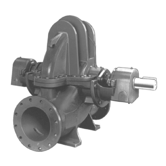
- Page 1 INSTRUCTION MANUAL AC5657C G&L Pumps Series A-C 9100 Base Mounted Centrifugal Pumps...
-
Page 3: Table Of Contents
Table of Contents Table of Contents 1 Introduction and Safety......................3 1.1 Introduction.......................... 3 1.2 Safety............................. 3 1.2.1 Safety terminology and symbols.................3 1.2.2 Safety instruction decals....................4 1.3 User safety..........................5 1.3.1 Wash the skin and eyes....................6 1.4 Protecting the environment....................6 2 Transportation and Storage...................... - Page 4 Table of Contents 6 Maintenance..........................27 6.1 Maintenance schedule...................... 27 6.2 Flood-damaged pumps....................28 6.3 Bearing maintenance......................28 6.3.1 Regrease the grease-lubricated bearings............... 29 6.3.2 Lubricating grease requirements................30 6.4 Shaft-seal maintenance..................... 30 6.4.1 Mechanical seal maintenance................... 30 6.4.2 Packed stuffing box maintenance................31 6.5 Cleaning without dismantling the pump................
-
Page 5: Introduction And Safety
This includes any modification to the equipment or use of parts not provided by Xylem. If there is a question regarding the intended use of the equipment, please contact a Xylem representative before proceeding. -
Page 6: Safety Instruction Decals
1 Introduction and Safety Hazard level Indication A hazardous situation which, if not avoided, could result WARNING: in death or serious injury A hazardous situation which, if not avoided, could result CAUTION: in minor or moderate injury Notices are used when there is a risk of equipment NOTICE: damage or decreased performance, but not personal injury. -
Page 7: User Safety
1 Introduction and Safety RATING PLATE ROTATING COMPONENTS DISCONNECT AND LOCK OUTPOWER BEFORE SERVICING. DO NOT OPERATE WITHOUT ALL GUARDS IN PLACE. CONSULT INSTALLATION AND SERVICE INSTRUCTION SHEET BEFORE OPERATING OR SERVICING. FAILURE TO FOLLOW INSTRUCTIONS COULD RESULT IN INJURY OR DEATH. -
Page 8: Wash The Skin And Eyes
• Clean-up of spills Exceptional sites CAUTION: Radiation Hazard Do NOT send the product to Xylem if it has been exposed to nuclear radiation, unless Xylem has been informed and appropriate actions have been agreed upon. Recycling guidelines Always follow local laws and regulations regarding recycling. -
Page 9: Transportation And Storage
2 Transportation and Storage 2 Transportation and Storage 2.1 Examine the delivery 2.1.1 Examine the package 1. Examine the package for damaged or missing items upon delivery. 2. Record any damaged or missing items on the receipt and freight bill. 3. - Page 10 2 Transportation and Storage • Pump end only (bare pump) • Pump less motor • Pump, motor, & baseplate Use the following recommended ways of handling HSC pump assemblies. • The pump assembly should remain horizontal during transport and lifting. •...
- Page 11 2 Transportation and Storage Figure 2: Lift using a forklift 30° MAX. Figure 3: Vertical - Half Pedestal - Model 200 • Place nylon sling, chain or wire rope around both flanges. Use a latch hook or standard shackle and end loops. Be sure the lifting equipment is of sufficient length to keep the lift angle less than 30°...
-
Page 12: Storage Requirements
2 Transportation and Storage NOTICE: Protect the product against humidity, heat sources, and mechanical damage. NOTICE: Do not place heavy weights on the packed product. 2.3 Storage requirements If the unit will not be installed and put into operation immediately upon arrival at the site, or for an extended shutdown after the unit is in operation, the following requirements for short-term storage apply: •... -
Page 13: Product Description
3 Product Description 3 Product Description 3.1 General description Description The pump is a centrifugal, frame-mounted pump. The following pump features make it easy to install, operate, and service: • High efficiency • Rugged construction • Compact design • Foot-mounted volute •... - Page 14 3 Product Description Nameplate G&L PUMPS 1. Impeller diameter 2. Pump rotation — for example, LHR = left hand rotation 3. Pump size — for example, 8 x 8 x 17M 4. Serial number — for example, 1–21937–1–1 5. Driver HP 6.
-
Page 15: Installation
(See the nameplate on the drive unit to select properly-sized overloads.) NOTICE: Supervision by an authorized Xylem representative is recommended to ensure proper installation. Failure to do so may result in equipment damage or decreased performance. 4.1.1 Pump location guidelines WARNING: Assembled units and their components are heavy. -
Page 16: Typical Installation
4 Installation 4.1.2 Typical installation 1. Compression tank (locate the compression tank on the suction side of the pump) 2. Air separator 3. Supply to system 4. Circuit setter 5. Triple duty valve 6. Isolation valve 7. From boiler chiller or converter 8. -
Page 17: Level The Base On A Concrete Foundation
4 Installation 1. Foundation bolt 2. Pipe sleeve 3. Washer 4. Built-up concrete foundation 4.1.4 Level the base on a concrete foundation 1. Place the pump on its concrete foundation. 2. Place 1.00 in./(25.40 mm) thick steel shims or wedges on both sides of each anchor bolt in order to support the pump . -
Page 18: Coupling Alignment
4 Installation – Puddle with a vibrator. – Pump the grout into place. 5. After the grout has thoroughly hardened, check the foundation bolts and tighten if necessary. Check alignment after tightening the bolts. 6. After the grout has dried, apply an oil base paint to the exposed edges to prevent moisture from coming in contact with the grout. - Page 19 4 Installation Do not rotate the shafts. c) Reposition the equipment until the offset is within the permissible range. See Maximum allowable misalignment for couplings. A coupling with a 3° angular misalignment will have a 0.191 in. (0.485 cm) difference in measurements between L1 and L2. This is within the 0° to 4° misalignment that is allowed for that size of coupling.
-
Page 20: Align The Pump Using A Dial Indicator
4 Installation 4.2.3 Align the pump using a dial indicator • Make sure that each hub is secured to its respective shaft and that all connecting and/or spacing elements are removed at this time. • The gap between the coupling hubs is set by the manufacturer before the units are shipped. -
Page 21: Final Alignment
4 Installation 4.2.4 Final alignment You cannot perform the final alignment until you initially operate the pump long enough to reach operating temperature. When the pump reaches the normal operating temperature, then secure the pump and re-check the alignment. Make sure that you compensate for temperature accordingly. -
Page 22: Suction Piping Checklist
4 Installation Check Explanation/Comment Always run piping to the pump. Do not move pump to pipe. This could make final alignment impossible. Check that the suction and discharge piping are This helps to avoid strain on the pump when the flange supported independently near the pump and properly bolts are tightened. - Page 23 4 Installation Check Explanation/comment Checked (Optional) You can install a short section of This facilitates the cleansing of the liquid passage of pipe adjacent to the suction flange such as the pump without dismantling the pump. With this Dutchman or a spool piece that is designed arrangement, anything that clogs the impeller is so that it can be readily dropped out of the accessible with the removal of the spool piece or pipe...
- Page 24 4 Installation 1. Air pocket Figure 11: Suction pipe installed with a reducer – incorrect 1. Air pocket Figure 12: Incorrect 1. No air pockets 2. Gradual rise Figure 13: Correct 1. No air pockets 2. Eccentric reducer 3. Gradual rise Figure 14: Gradual rise to the pump –...
-
Page 25: Commissioning, Startup, Operation, And Shutdown
5 Commissioning, Startup, Operation, and Shutdown 5 Commissioning, Startup, Operation, and Shutdown 5.1 Preparation for startup WARNING: • Failure to follow these precautions before you start the unit will lead to serious personal injury and equipment failure. • Do not operate the pump below the minimum rated flows or with the suction or discharge valves closed. -
Page 26: Priming
5 Commissioning, Startup, Operation, and Shutdown 9. Assure that pump is full of liquid (see priming) and all valves are properly set and operational, with the discharge valve closed, and the suction valve open. 10.Check rotation. Be sure that the driver operates in the direction indicated by the arrow on the pump casing as serious damage can result if the pump is operated with incorrect rotation. -
Page 27: Freezing Protection
5 Commissioning, Startup, Operation, and Shutdown 5.1.6 Freezing protection NOTICE: Do not expose an idle pump to freezing conditions. Drain all liquid that is inside the pump and connected pipes. Failure to do so can cause liquid to freeze and damage the pump. Pumps that are shut down during freezing conditions should be protected by one of the following methods: •... - Page 28 5 Commissioning, Startup, Operation, and Shutdown Figure 18: Main joint bolts G&L Pumps Series A-C 9100 Base Mounted Centrifugal Pumps INSTRUCTION MANUAL...
-
Page 29: Maintenance
6 Maintenance 6 Maintenance 6.1 Maintenance schedule CAUTION: Shorten the inspection intervals if the pumped liquid is abrasive or corrosive, or if the environment is classified as potentially explosive. NOTICE: This timetable assumes that the unit has been constantly monitored after startup. Adjust the timetable for any extreme or unusual applications or conditions. -
Page 30: Flood-Damaged Pumps
6 Maintenance figures of the last test. This is especially important where the pumped liquid tends to form a deposit on internal surfaces. • Inspect foot valves and check valves. A faulty foot or check valve will cause poor performance. The check valve safeguards against water hammer when the pump stops. -
Page 31: Regrease The Grease-Lubricated Bearings
6 Maintenance A Mobile Oil, DTE Medium, or equal, meeting the following specification will provide satisfactory lubrication. Similar oils can be furnished by all major oil companies. It is the responsibility of the oil vendor to supply a suitable lubricant. Saybolt viscosity at 100°F 215 SSU-240 SSU Saybolt viscosity at 210°F... -
Page 32: Lubricating Grease Requirements
6 Maintenance 1. With fully enclosed coupling guards, regrease pump while pump is running. a) With old style open ended guards, stop pump, re-grease, and hand turn shaft before re-starting. 2. Wipe dirt from the grease fittings before greasing. 3. Fill both of the grease cavities through the fittings with the recommended grease. Stop when grease leaks out at shaft. -
Page 33: Packed Stuffing Box Maintenance
6 Maintenance 6.4.2 Packed stuffing box maintenance Check or instruction Explanation/comment When starting a pump with fiber packing for Never draw the gland to the point where the packing is compressed the first time, make sure that the packing is too tightly and no leakage occurs. -
Page 34: Drain The Pump
6 Maintenance NOTICE: Make sure that all replacement parts are available before you disassemble the pump for overhaul. 6.6.2 Drain the pump CAUTION: • Allow all system and pump components to cool before you handle them to prevent physical injury. 1. -
Page 35: Disassemble The Pump With Packing On Shaft Sleeve
6 Maintenance 1. Outer guard 2. Inner guard 3. Attach the support bracket inline with the bolt 4. Support bracket 5. Nut 6. Lockwasher 7. Capscrew 8. Flat washer 9. Spacer washer 10.Option used instead of the spacer where overall guard length exceeds 12 in. (30 cm) or the guard width is over 10 in. -
Page 36: Pre-Assembly Inspections
6 Maintenance hold the shaft vertically and drop it on a block of wood. The impeller weight should force both the impeller and sleeve from the shaft. 16.For impellers with replaceable rings, remove the rings (4–004–9) by cutting the rings with a cold chisel. -
Page 37: Dimensions
6 Maintenance 6.8 Dimensions Figure 21: Cross section Quantity Pump size Dimension A 2–904–9 12x8x22M 13.50 12x8x22L 14x10x20S 16x12x23 15.81 16x14x17 18x14x23 14x10x20L 16.60 6.9 Reassembly 6.9.1 Reassemble the pump with the mechanical seals on the shaft sleeve All bearings, O-rings, seals, and gaskets should be replaced with new parts during assembly. - Page 38 6 Maintenance 7. Assemble casing rings (3–003–9). See figure for adjustable rings. 8. Install stationary seats (3–401–0) onto the glands (3–014–2) with lapped surface facing outward. Do not scratch or damage seal faces during assembly. Stationary seat must bottom squarely in gland. 9.
- Page 39 6 Maintenance Figure 23: Oil lubricated bearing housing 12.Slide deflectors (3–136–9) and bearing covers (3–018–3), –4) on the shaft. Install snap rings (3–915–9). Install thrust washer (3–078–9) on the outboard end. For ease of assembly and protection of rubber parts while sliding parts onto shaft, cover O-ring groove, keyways, and threads with electrical tape.
-
Page 40: Reassemble The Pump With The Packing On The Shaft Sleeve
6 Maintenance 24.Lower upper half casing (2–001–7) into place and locate using the taper dowels (2– 916–9) and install casing main joint bolts (2–904–9). The casing joint bolts should be tightened to the following torques: 300 ft-lb minimum for .75"-10 Ferry Cap Counterbore screws (Grade 8), 400 ft-lb minimum for 1.0”-8 Ferry Cap Counterbore screws (Grade 8). - Page 41 6 Maintenance gasket material on the casing joint and mark it by pressing it against the edges of the casing. Trim the gasket so that it is flush with the inside edges of the casing. 1. Place impeller key (3–911–1) in shaft (3–007–0). 2.
- Page 42 6 Maintenance NOTE: Sliding inboard bearing housing toward coupling before assembling rotating element in casing will ease assembly. 18.Bolt outboard bearing housing in place. Be sure that both housings are seated in lower half casing. 19.Bolt inboard bearing housing in place. 20.Clean the gasket surfaces of the casing.
-
Page 43: Install The Hex Coupling Guard
6 Maintenance 6.9.3 Install the hex coupling guard 1. Slide the inner guard into the outer guard. 2. Spread the guards and place them over the coupling. Do not spread the inner and outer guards more than necessary for guard installation, as it can alter their fit and appearance. -
Page 44: Install The Oil Ring
6 Maintenance 4. Impeller 5. Casing 6. Locking pin Disassembly and reassembly Adjustable rings are removed in the same manner as standard casing rings. They can be separated for cleaning. Adjustable rings are installed in the pump with stationary and the adjustable members assembled but not pinned. -
Page 45: Limited End Float Coupling
6 Maintenance 3. Unscrew the reservoir and remove. 4. Flush the oiler and bearing housing with a light grade of oil. Flush until all foreign particles have been removed. 5. Screw the pipe plug and vent assembly back into place. 6. - Page 46 6 Maintenance For normal service, with repairs to be made in the field, the following parts are recommended for stock. • 1 set of bearings • 1 set of wearing rings • 1 set of gaskets, O-rings, and grease seals •...
-
Page 47: Troubleshooting
7 Troubleshooting 7 Troubleshooting 7.1 Operation troubleshooting Between regular maintenance inspections, be alert for signs of motor or pump trouble. Correct any trouble immediately and avoid costly repair and shutdown. Symptom Cause Remedy Lack of prime Fill pump and suction pipe completely with liquid. - Page 48 7 Troubleshooting Symptom Cause Remedy Air leaks in suction piping If liquid pumped is water or other non-explosive, and explosive gas or dust is not present, test flanges for leakage with flame or match, or by plugging inlet and putting line under pressure.
- Page 49 7 Troubleshooting Symptom Cause Remedy Mechanical defects See “Defective impeller” and “Foot valve too small or partially obstructed”. Obstruction in liquid passages. Dismantle pump and inspect passages of impeller and casing. Remove obstruction. Air or gases in liquid. (Test in May be possible to over rate pump to laboratory, reducing pressure on point where it will provide adequate...
- Page 50 7 Troubleshooting Symptom Cause Remedy Suction inlet not immersed enough. If inlet cannot be lowered, or if eddies through which air is sucked persist when it is lowered, chain a board to suction pipe. It will be drawn into eddies, smothering the vortex. Liquid heavier (in either viscosity or Use larger driver.
-
Page 51: Parts Listings And Cross-Sectional Drawings
8 Parts Listings and Cross-Sectional Drawings 8 Parts Listings and Cross-Sectional Drawings 8.1 Parts list G&L Pumps Series A-C 9100 Base Mounted Centrifugal Pumps INSTRUCTION MANUAL... - Page 52 8 Parts Listings and Cross-Sectional Drawings Quantity Part number Part name Packing Mechanical seal 0–901–0 Valve 2 (optional) 0–910–0 Pipe plug 0–950–0 Pipe nipple 2 (optional) 0–952–0 Tubing 2 (optional) 1–013–2 Seal cage 1–014–2 Gland (packing) 1–428–1 Sleeve gasket 1–904–9 Gland and housing bolt 1–909–9 Washer, gland bolt...
- Page 53 8 Parts Listings and Cross-Sectional Drawings Quantity Part number Part name Packing Mechanical seal 3–914–2* O-ring (gland) 3–914–9* O-ring (shaft sleeve) 3–915–9 Snap ring 3–943–9 Spirol pin 4–002–0 Impeller 4–004–9 Impeller ring 2 (optional) 2 (optional) * Recommended Spare parts G&L Pumps Series A-C 9100 Base Mounted Centrifugal Pumps INSTRUCTION MANUAL...
-
Page 54: Product Warranty
9 Product warranty 9 Product warranty Commercial warranty Warranty. For goods sold to commercial buyers, Seller warrants the goods sold to Buyer hereunder (with the exception of membranes, seals, gaskets, elastomer materials, coatings and other "wear parts" or consumables all of which are not warranted except as otherwise provided in the quotation or sales form) will be (i) be built in accordance with the specifications referred to in the quotation or sales form, if such specifications are expressly made a part of this Agreement, and (ii) free from defects in material and... - Page 55 9 Product warranty Limited consumer warranty Warranty. For goods sold for personal, family or household purposes, Seller warrants the goods purchased hereunder (with the exception of membranes, seals, gaskets, elastomer materials, coatings and other "wear parts" or consumables all of which are not warranted except as otherwise provided in the quotation or sales form) will be free from defects in material and workmanship for a period of one (1) year from the date of installation or eighteen (18) months from the product date code, whichever shall occur first, unless a...
- Page 56 9 Product warranty To make a warranty claim, check first with the dealer from whom you purchased the product or visit www.xyleminc.com for the name and location of the nearest dealer providing warranty service. G&L Pumps Series A-C 9100 Base Mounted Centrifugal Pumps INSTRUCTION MANUAL...
- Page 60 For more information on how Xylem can help you, go to www.xylem.com Xylem Inc. Visit our Web site for the latest version of this document...
Need help?
Do you have a question about the G&L A-C 9100 Series and is the answer not in the manual?
Questions and answers