
Related Manuals for Pulsar PSDC 161214


Summary of Contents for Pulsar PSDC 161214
- Page 1 PSDC 161214 v.1.0 PSDC 12V/14A/16x1A Switched mode power supply for CCTV. Edition: 4 from 26.07.2013 Supersedes the 3 from 10.12.2012 edition...
- Page 2 PSDC161214 Features: • • supply output 16x 0,87A/12V DC AW technical output of fuse activation • indication output voltage adjustment 12V÷ 15VDC • • protections: 16 outputs protected with 1A fuses • • SCP short-circuit protection jumper selectable fuses: glass fuse or polymer •...
- Page 3 PSDC161214 1.3. Description of PSU components and connectors. Table 1. Elements of the PSU pcb (see fig. 2). Element no. Description L1…..L8 (green) LEDs (indicating fuse activation) F1…F8 glass fuses in AUX (+) circuits IN supply input of the LB8/AW strip AUX1….
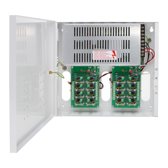
- Page 4 PSDC161214 Fig.3. The view of the PSU. 1.4. Specifications: - electrical specifications (tab.3) - mechanical specifications (tab.4) - operation safety (tab.5) - operating specifications (tab.6) Electrical specifications (tab. 3). Supply voltage 176 ÷ 264V AC Current consumption 1,36A@230VAC max.
- Page 5 PSDC161214 Mechanical specifications (tab. 4). Enclosure dimensions 280 x 256 x 58 (285 x 261 x 50+8) (WxHxD) [mm] (+/- 2) Fixing 247 x 225 x Φ 6 (WxH) Net/gross weight 2,35/2,48 kg Enclosure Steel plate, DC01 0,7mm colour: RAL 9003...
- Page 6 PSDC161214 The shock protection circuit shall be performed with a particular care, i.e. the yellow and green wire coat of the power cable shall stick to one side of the terminal marked with the ‘ ’ earth symbol in the PSU enclosure. Operation of the power supply without a properly made and fully operational shock protection circuit is UNACCEPTABLE! It can result in device damage or an electric shock.
- Page 7 PSDC161214 Fig. 5. Electrical diagram of the OC output. • TAMPER – output indicating unwanted opening of the PSU, contains volt-free (potential-free) contacts indicating the door status - unit closed: NC, unit opened: NO. 4. Operation and use. 4.1 Overload or short circuit at the PSU output.
- Page 8 WEEE separately. GENERAL WARRANTY CONDITIONS 1. Pulsar K. Bogusz Sp.j. (the manufacturer) grants a two-year warranty for the equipment, counted from the device’s production date. 2. The warranty includes free-of-charge repair or replacement with an appropriate equivalent (the selection is at the manufacturer’s discretion) if the malfunction is due to the manufacturer, includes manufacturing or material defects, unless such...
Need help?
Do you have a question about the PSDC 161214 and is the answer not in the manual?
Questions and answers