
Related Manuals for Pulsar PSDC 161214


Summary of Contents for Pulsar PSDC 161214
- Page 1 PSDC 161214 v.1.0 PSDC 12V/14A/16x1A Switched mode power supply for CCTV. Edition: 1st (10th Mar2012)
- Page 2 PSDC161214 Features: • • supply output 12VDC/14A AW technical output of fuse activation • indication output voltage adjustment 12V÷ 15VDC • • protections: 16 outputs, protected with 1A fuses or • polyswitches, jumper selectable SCP short-circuit protection • •...
- Page 3 PSDC161214 1.3. Description of PSU components and connectors. Table 1. Elements of the PSU pcb (see fig. 2). Element no. Description L1…..L8 (green) LEDs (indicating fuse activation) F1…F4 fuse element of safety devices in AUX circuits (+) IN supply output of the LB8/AW strip AUX1….
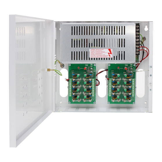
- Page 4 PSDC161214 Fig.3. The view of the PSU.
- Page 5 PSDC161214 1.4. Specifications: - electrical specifications (tab.3) - mechanical specifications (tab.4) - operation safety (tab.5) - operating specifications (tab.6) Electrical specifications (tab. 3). Supply voltage 176 ÷ 264 V AC Current consumption 1,36A@230VAC max. Power frequency 50Hz PSU power 200 W max.
- Page 6 PSDC161214 2. Installation. 2.1 Requirements The regulated PSU is to be mounted by a qualified installer, holding relevant permits and licenses (applicable and required for a given country) for 230V/AC interference and low-voltage installations. The unit should be mounted in confined spaces, in accordance with the 2nd environmental class, with normal relative humidity (RH=90% maximum, without condensation) and temperature from -10°...
- Page 7 PSDC161214 Fig. 4 The view of the PSU panel. 3.2 Technical outputs. The PSU has an indication output that indicates the OC type fuse failure (LB8/AW A, B strip output). The AW technical output during correct operation of the LB8/AW is ground fault (-). Failure of one of the fuses causes disconnection from ground (hi-Z) and is indicated by the red diode on the LB8/AW strip.
- Page 8 GENERAL WARRANTY CONDITIONS 1. Pulsar K. Bogusz Sp.j. (the manufacturer) grants a two-year warranty for the equipment, starting from the initial product date of purchase placed on the receipt. 2. If a purchase proof is missing, a three-year warranty period is counted from the device’s production date.
Need help?
Do you have a question about the PSDC 161214 and is the answer not in the manual?
Questions and answers