Table of Contents
Advertisement
Quick Links
Advertisement
Table of Contents

Related Manuals for Promac PBD-2555V


Summary of Contents for Promac PBD-2555V
- Page 1 Metal Lathe PBD-2555V Metalldrehbank Tour à métaux France Schweiz / Suisse TOOL France / PROMAC JPW (TOOL) AG 57, rue du Bois Chaland, Z.I. du Bois Chaland Tämperlistrasse 5 case postale 2935 FR-91029 Evry Cedex CH-8117 Fällanden Switzerland www.promac.fr...
- Page 2 CE‐Conformity Declaration CE‐Konformitätserklärung Déclaration de Conformité CE Product / Produkt / Produit: Metal lathe / Metalldrehbank / Tour à métaux PBD‐2555V Brand / Marke / Marque: PROMAC Manufacturer / Hersteller / Fabricant: JPW (Tool) AG, Tämperlistrasse 5, CH‐8117 Fällanden Schweiz / Suisse / Switzerland We hereby declare that this product complies with the regulations Wir erklären hiermit, dass dieses Produkt der folgenden Richtlinie entspricht Par la présente, nous déclarons que ce produit correspond aux directives suivantes 2006/42/EC Machinery Directive Maschinenrichtlinie Directive Machines 2014/30/EU electromagnetic compatibility elektromagnetische Verträglichkeit compatibilité électromagnétique designed in consideration of the standards und entsprechend folgender zusätzlicher Normen entwickelt wurde et été développé dans le respect des normes complémentaires suivantes EN ISO 12100:2010 EN ISO 23125:2015 EN 60204‐1:2006/AC2010 EN 61000‐6‐2:2005 EN 61000‐6‐4:2007/A1:2011 Responsible for the Documentation / Dokumentations‐Verantwortung / Responsabilité de Documentation: ...
-
Page 3: Table Of Contents
EN Operating Instructions (Original) 1.0 About this Manual This manual is provided by PROMAC, covering the safe operation and maintenance procedures for a PROMAC Model PBD‐ 2555V Metal Lathe. This manual contains instructions on installation, safety precautions, general operating procedures, maintenance instructions and parts breakdown. The machine has been designed and constructed to provide consistent, long‐ term operation if used in accordance with the instructions as set forth in this document. Retain this manual for future reference. If the machine transfers ownership, the manual should accompany it. 2.0 Table of Contents Section Page 1.0 About this manual ................................ 3 2.0 Table of contents ................................ 3 3.0 Important safety instructions ............................ 4~6 3.1 Designated use and limitations to use ........................ 6 ... -
Page 4: Important Safety Instructions
18. Keep the floor around the machine clean and free of scrap material, oil and grease. Do not use this machine for other than its intended use. If used for other purposes, PROMAC disclaims any real or 19. Keep visitors a safe distance from the work area. Keep implied warranty and holds itself harmless from any injury children away. that may result from that use. 20. Make your workshop child proof with padlocks, master ... - Page 5 Familiarize yourself with the following safety notices used in this manual: WARNING: This means that if precautions are not heeded, it may result in serious, or possibly even fatal, injury. CAUTION: This means that if precautions are not heeded, it may result in minor injury and/or possible machine damage. SAVE THESE INSTRUCTIONS WARNING: These symbols blow advise that you follow the correct safety procedures when using this machine. Read and understand the entire user manual before attempting assembly or Any work piece stock extending the rear ...
-
Page 6: Designated Use And Limitations To Use
3.1 Designated use and limitations to use The machine is designed for turning and drilling machinable metal and plastic materials only. The workpiece must allow to safely be loaded, supported and clamped. The machine is intended for indoor use. The protection rating of the electrical installation is IP 54. To avoid tipping, the machine must be bolted down with four anchor bolts. If used for other purposes, PROMAC disclaims any real or implied warranty and holds itself harmless from any injury that may result from that use. WARNING: The machine is not suitable for machining magnesium…high danger to fire ! Never place your fingers in a position where they could contact any rotating parts or chips. Check the save clamping of the work piece before starting the machine. Don’t exceed the clamping range of the chuck. Work pieces longer than 3 times the chucking diameter need to be supported by the tailstock or a steady rest. Avoid small chucking diameters at big turning diameters. Avoid short chucking lengths and small chucking contact. Do not exceed the max speed of the work holding device. Use the right tool at the correct speed and feed rate. Do not force a tool or attachment to do a job for which it was not designed. The right tool will do the job better and more safely. Use recommended accessories; improper accessories may be hazardous. Maintain tools with care. Keep cutting tools sharp and clean for the best and safest performance. Follow instructions for lubricating and changing accessories. Do not attempt to adjust or remove tools during operation. Never stop a rotating chuck or workpiece with your hands. Choose a small spindle speed when working unbalanced work pieces and for threading and tapping operations. Any work piece stock extending the rear end of the headstock must be covered on its entire length. High danger of injury! Long work pieces may need a steady rest support. A long and thin work piece can suddenly bend at high speed rotation. Never move the tailstock or tailstock quill while the machine is running. Remove cutting chips with the aid of an appropriate chip hook when the machine is at a standstill only. Measurements and adjustments may be carried out when the machine is at a standstill only. Maintenance and repair work may only be carried out after the machine is protected against accidental starting, pull the mains plug. Remove loose items and unnecessary work pieces from the area before starting the machine. Rotate workpiece by hand before applying power. Use lowest speed when starting new workpiece. Tighten all locks before operating. 3.2 Remaining hazards When using the machine according to regulations some remaining hazards may still exist. The rotating work piece and chuck can cause injury. Thrown and hot work pieces and cutting chips can lead to injury. Chips and noise can be health hazards. Be sure to wear personal protection gear such as safety goggles and ear protection. The use of incorrect mains supply or a damaged power cord can lead to injuries caused by electricity. ... -
Page 7: Specifications
4.0 Specifications Model number .................................... P BD‐2555V Stock number……………………………………………………………………. ...................... P BD‐2555V Motor and electricals: Motor type……………………………………………………. .................... D C‐motor, variable speed Motor power .................................... 1 .1 kW Power supply ................................ 1 ~230V, PE, 50Hz Protection class .................................... I P54 Listed load amps .................................... 6 A Machine lamp .............................. Halogen lamp 24V, 35 W Coolant pump .................................... 40 W ... - Page 8 4.1 Spindle nose mounting: Figure 4‐1: Spindle nose mounting 4.2 Anchor bolt hole pattern: Figure 4‐2: Anchor bolt pattern for lathe bed (left) & machine stand (right) WARNING: To avoid tipping, the machine must be bolted down with four anchor bolts (not provided). ...
-
Page 9: Machine Description
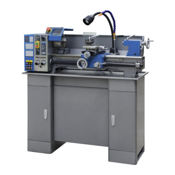
5.0 Machine Description Figure 5‐2: Machine description R ........... Feed speed select knob S ........ Feed forward/off/reverse T ............ Coolant ON/OFF U .......... S pindle power ON/OFF V ......... Spindle forward/reverse Figure 5‐1: Machine description W ........ Variable speed select knob X ............Emergency Stop A .......... Machine cabinet stand Y .......... Spindle speed display B .............. Gear box Z ........... Apron hand wheel ... -
Page 10: Setup And Assembly
To avoid tipping, the machine must be bolted down with four 6.0 Setup and Assembly anchor bolts (not provided). To avoid twisting the bed, make sure the setup surface is absolutely flat and level. WARNING: Loosen anchor bolts, shim and tighten bolts if needed. Read and understand the entire contents of this manual The machine must be level to be accurate ! before attempting assembly or operation. Failure to comply may cause serious injury. ... -
Page 11: Extension Cords
8.2 Change gear setup Repair or replace damaged or worn cord immediately. Remove the pulley cover. 7.2 Extension cords The rotational speed of the lead screw, and hence the rate of The use of extension cords is discouraged; try to position feed of the cutting tool, is determined by the gear machines near the power source. If an extension cord is configuration and by the feed speed select lever (R, Fig 5‐2). necessary, make sure it is in good condition. Assemble the gears with desired setup (Fig 8‐2) An undersized cord will cause a drop in line voltage resulting in loss of power and overheating. Only use extension cords marked H07RN‐F, with wires 1,5mm2 ... -
Page 12: Taper Turning With Tailstock
8.3 Taper turning with tailstock 8.5 Three jaw universal chuck Mount the work piece fitted with the drive dog between With this universal chuck, cylindrical, triangular and hexagonal centres. The drive dog is driven by the face plate. stock may be clamped (Fig 8‐5). Lubricate the tailstock centre with grease to prevent tip from overheating. Figure 8‐5: Three jaw universal chuck To hold big diameter stock, a set of OD chuck jaws is supplied. The jaws need to be inserted to the chuck in the correct order. Use Molykote Paste G (or adequate grease) to lubricate the jaws. Figure 8‐3: Taper turning between centres To turn a taper, offset the tailstock, loosen the locking screws 8.6 Four jaw independent chuck (Optional) (Z, Fig 8‐3) and use screws (Y) to adjust. This chuck has four independently adjustable chuck jaws (Fig After ... -
Page 13: Live Centre
8.7 Live centre (Optional) The live centre (Fig 8‐7) is mounted in ball bearings. Its use is highly recommended for speeds above 500 RPM. Figure 8‐7: Live centre To eject the live centre, fully retract the tailstock quill. Figure 8‐9: Follow rest Set the fingers (2) snug but not overly tight. Lubricate the fingers to prevent premature wear. 8.8 Steady rest and follow rest The rests prevent flexing of long and thin work pieces under pressure from the tool. The steady rest (Fig 8‐8) serves as a support for longer shafts and ensures a safe and chatter free operation. Figure 8‐8: Steady rest The follow rest (Fig 8‐9) is mounted on the carriage and follows the movement of the tool. ... -
Page 14: Operating Controls
10.2 Chucking 9.0 Operating Controls Do not exceed the max speed of the work holding device. Refer to Figure 9‐1: Jaw teeth and scroll must always be fully engaged. Otherwise R ............ Feed select knob chuck jaws may break and fly off in rotation (Fig 10‐1). S ........... Feed forward/off/reverse T ............ C oolant ON/OFF U .......... Spindle power ON/OFF V .......... Spindle forward/reverse W ........ Variable speed select knob X ............ Emergency Stop Y .......... S pindle speed display Figure 10‐1: Poor jaw engagements Avoid long workpiece extensions. Parts may bend (Fig 10‐2) or fly off (Fig 10‐3). Use tailstock or rest to support. ... -
Page 15: Cutting Tool Setup
10.3 Cutting Tool Setup The cutting angle is correct when the cutting edge is in line with the centre axis of the work piece. Use the point of the tailstock centre as a gauge and shims under the tool to obtain the correct centre height (Fig 10‐5). Figure 10‐6: Machine controls The correct feed depends on the material to be cut, the cutting operation, the type of tool, the rigidity of the work piece Figure 10‐5: Cutting tool setup ... -
Page 16: Thread Cutting
10.7 Thread cutting 11.0 User‐Maintenance Threading is performed in multiple passes with a threading tool. WARNING: Each depth of cut should be about 0,2mm and become less for Before any intervention on the machine, disconnect it from the finishing passes. electrical supply, pull the mains plug. Failure to comply may A) To cut inch and metric threads cause serious injury. Set the machine up for the desired threading pitch (see An important security factor is the cleaning of the machine, of chapter 8.2). bed, carriage and slides, of the floor and the surrounding places. Select the lowest possible spindle speed. Loose objects could come into contact with the moving chuck Engage the halve nut (CC, Fig 10‐6). or workpiece, creating hazards. NOTE: The halve nut must stay engaged during the entire Empty the chip tray regularly. ... -
Page 17: Troubleshooting
12.0 Troubleshooting Symptom Possible Cause Correction * Lathe unplugged from wall, or motor. Check all plug connections. Fuse blown, or circuit breaker tripped. Replace fuse, or reset circuit breaker. Lathe will not start. Cord damaged. Replace cord. Chuck guard not closed. Close chuck guard. Pulley cover removed Install pulley cover Extension cord too light or too long. Replace with adequate size and length cord. Lathe does not come up to speed. Low current. Contact a qualified electrician. Base on uneven surface. Locate lathe on even floor. Lathe not bolted to the floor Bolt machine to the floor Unbalanced workpiece Reduce speed Improve chucking length or diameter, support Workpiece deflection on tailstock end Lathe vibrates excessively. Tool deflection Reduce tool length Slide backlash Adjust slides Slides running dry Lubricate with oil Dull tool tip Re‐sharpen or change tool Chip load too high Reduce depth of cut or feed Dry change gear hubs. ... -
Page 18: Replacement Parts
15.0 Replacement Parts PBD‐2555V Assembly Breakdown ‐1 ... - Page 19 PBD‐2555V Parts List for Breakdown ‐1 Index Part No. No. Description Size Qty. 102 .. PBD2555V‐1 ...... F LAT KEY .............. 4 x 12 mm ..... 1 107 .. PBD2555V‐1‐107.... L ATHE BED ............... ........ 1 108 .. PBD2555V‐2 ...... H EXAGON SOCKET SCREW M8×12 ...... M8×12 ...... 1 109 .. PBD2555V‐3 ...
- Page 20 PBD‐2555V Assembly Breakdown ‐2 ...
- Page 21 PBD‐2555V Parts List for Breakdown ‐2 Index Part No. No. Description Size Qty. 401 .. PBD2555V‐2‐401.... C HARACTERISTICS PLATE ........ ........ 1 402 .. PBD2555V‐8 ...... F ASTENING SCREW .......... M 4×10 ...... 6 403 .. PBD2555V‐2‐403.... P ROTECTIVE COVER OF THREADED ROD .... ........ 2 404 .. PBD2555V‐9 ...... N UT ................. M 10 ...... 4 405 .. PBD2555V‐2‐405.... K NURL NUT ............. ........ 2 406 .. PBD2555V‐2‐406.... ...
- Page 22 PBD‐2555V Assembly Breakdown ‐3 ...
- Page 23 PBD‐2555V Parts List for Breakdown ‐3 Index Part No. No. Description Size Qty. 301 .. PBD2555V‐30 ...... L OCK WASHER ............ Φ 12 ...... 1 302 .. PBD2555V‐3‐302.... G EARWHEEL ............ ........ 1 303 .. PBD2555V‐31 ...... L OCK WASHER ............ Φ 12 ...... 1 304 .. PBD2555V‐3‐304.... S HAFT C .............. ........ 1 305 .. PBD2555V‐3‐305.... ...
- Page 24 PBD‐2555V Assembly Breakdown ‐4 ...
- Page 25 PBD‐2555V Parts List for Breakdown ‐4 Index Part No. No. Description Size Qty. 501 .. PBD2555V‐47 ...... O IL NIPPLE ............... ........ 2 502 .. PBD2555V‐48 ...... H EXAGONAL SOCKET HEAD SCREW DIN 912 .. M 8×35 ...... 1 503 .. PBD2555V‐4‐503.... C HANGE GEAR RAIL .......... ........ 1 504 .. PBD2555V‐4‐504.... B EARING PEDESTAL .......... ........ 1 505 .. PBD2555V‐49 ...
- Page 26 PBD‐2555V Assembly Breakdown ‐5 ...
- Page 27 PBD‐2555V Parts List for Breakdown ‐5 Index Part No. No. Description Size Qty. 601 .. PBD2555V‐5‐601.... E CCENTER .............. ........ 1 602 .. PBD2555V‐51 ...... T APER PIN ............... 3 ×20 ...... 1 603 .. PBD2555V‐5‐603.... B USH .............. ........ 1 604 .. PBD2555V‐5‐604.... H OUSING .............. ........ 1 605 .. PBD2555V‐52 ...
- Page 28 PBD‐2555V Assembly Breakdown ‐6 ...
- Page 29 PBD‐2555V Parts List for Breakdown ‐6 Index Part No. No. Description Size Qty. 501 .. PBD2555V‐6‐501.... H ANDWHEEL ............ ........ 1 502 .. PBD2555V‐66 ...... B ALL OILER .............. 6 ......... 10 503 .. PBD2555V‐67 ...... F LAT KEY .............. 4 x 12 mm ..... 1 504 .. PBD2555V‐6‐504.... R OUND NUT ............ ........ 1 505 .. PBD2555V‐68 ...
- Page 30 PBD‐2555V Assembly Breakdown ‐7 ...
- Page 31 PBD‐2555V Parts List for Breakdown ‐7 Index Part No. No. Description Size Qty. 401 .. PBD2555V‐7‐401.... G RADUATED DIAL ........... ........ 1 402 .. PBD2555V‐7‐402.... I NTERMEDIATE FLANGE .......... ........ 1 403 .. PBD2555V‐84 ...... H EXAGON SOCKET SCREW ........ M 8×20 ...... 2 404 .. PBD2555V‐7‐404.... S LIDE GUIDE WAY ........... ........ 1 405 .. PBD2555V‐7‐405.... S TRAINING SCREW .......... ........ 1 406 .. PBD2555V‐85 ...... N UT M4 .............. ........ 3 407 .. PBD2555V‐86 ...
- Page 32 PBD‐2555V Assembly Breakdown ‐8 ...
- Page 33 PBD‐2555V Parts List for Breakdown ‐8 Index Part No. No. Description Size Qty. 904 .. PBD2555V‐8‐904.... PIECE OF CENTERING OF SPINDLE SLEEVE ... ........ 1 905 .. PBD2555V‐8‐905.... SPINDLE SLEEVE ............ ........ 1 906 .. PBD2555V‐8‐906.... SPINDLE .............. ........ 1 907 .. PBD2555V‐8‐907.... AXIALLY GROOVED BALL BEARING ....... 51101 ...... 1 910 .. PBD2555V‐99 ...... F LAT KEY .............. 4 x 14 mm ..... 1 911 .. PBD2555V‐8‐911.... ...
-
Page 34: Wiring Diagrams
16.0 Wiring Diagrams PBD‐2555V ……………….1~230V, PE, 50Hz ... - Page 35 PBD‐2555V Electrical Parts List Designation Model Quantity Note Electromagnetic switch KJD17GF 1 Reverse Switch F/R ZH‐A 1 EMC Filter 1 Emergency stop ZB2‐BE102C 1 Circuit board 1 Potentiometer WX14‐12 4K7 1 Speed display and sensor JD011 5V 1 DC Motor ...
Need help?
Do you have a question about the PBD-2555V and is the answer not in the manual?
Questions and answers