Table of Contents
Advertisement
Quick Links
Advertisement
Table of Contents

Related Manuals for Promac 941VA


Summary of Contents for Promac 941VA
- Page 1 941VA METAL LATHE Original: Operating Instructions France Schweiz / Suisse JPW (TOOL) AG TOOL France / PROMAC Tämperlistrasse 5 57, rue du Bois Chaland, Z.I. du Bois Chaland CH-8117 Fällanden Switzerland case postale 2935 FR-91029 Evry Cedex www.promac.ch www.promac.fr M-BD-941VA-M...
- Page 2 CE‐Conformity Declaration CE‐Konformitätserklärung Déclaration de Conformité CE Product / Produkt / Produit: Metal Lathe Metalldrehbank Tour à métaux 941VA Brand / Marke / Marque: PROMAC Manufacturer / Hersteller / Fabricant: JPW (Tool) AG, Tämperlistrasse 5, CH‐8117 Fällanden Schweiz / Suisse / Switzerland We hereby declare that this product complies with the regulations Wir erklären hiermit, dass dieses Produkt der folgenden Richtlinie entspricht Par la présente, nous déclarons que ce produit correspond aux directives suivantes 2006/42/EC Machinery Directive Maschinenrichtlinie Directive Machines 2014/30/EU electromagnetic compatibility elektromagnetische Verträglichkeit compatibilité électromagnétique designed in consideration of the standards und entspechend folgender zusätzlicher Normen entwickelt wurde et été développé dans le respect des normes complémentaires suivantes EN ISO 12100:2010 EN ISO 23125:2015 EN 60204‐1:2006+A1:2009 EN 61000‐6‐2:2005 EN 61000‐6‐4:2007+A1:2011 ...
-
Page 4: Table Of Contents
Table of Contents INTRODUCTION........................4 MAIN PARAMETERS……………………………………………………………………..5 SECTION 1: SAFETY.......................7 SECTION 2: POWER SUPPLY....................9 Availability………………………………………………………………………9 Circuit Requirements…………………………………………………………..9 Grounding & Plug Requirements…………………………………………….10 Extension Cords……………………………………………………………….10 SECTION 3: SETUP……………………………………………………………………...…11 Unpacking……………………………………………………………………...11 Inventory………………………………………………………………………11 Clean Up……………………………………………………………………….12 Installation Dimensions……………………………………………………….12 Check Gearbox Oil……………………………………………………………12 Open the Cover………………………………………………………………..13 Install belt and Chang speeds………………………………………………...13 Test Run Lathe………………………………………………………………...14 SECTION 4: OPERATE……………………………………………………………………..15 General…………………………………………………………………………15... -
Page 5: Introduction
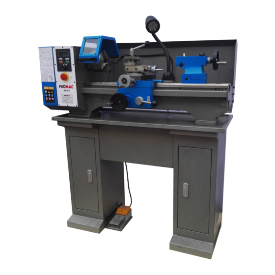
IDENTIFICATION The following is a list of controls and components on the lathe. Please take time to become familiar with each term and its location. These terms will be used throughout the manual and knowing them is essential to understanding the instructions and terminology used in this manual. -
Page 6: Main Parameters
Model 941VA Main Parameters Product Dimensions: Weight..........................180kg Width (side-to-side) x Depth (front-to-back) x Height........114 x 60 x 120 cm Shipping Dimensions: Type..........................Wood Crate Content..........................Machine Weight..........................225 Length x Width x Height..................123 x 73 x 140.cm Electrical: Minimum Circuit Size......................10 amp Switch........................Forward/Reverse... - Page 7 Tailstock Info Tailstock Taper........................MT#2 Tailstock Barrel Diameter....................Φ30 mm Tailstock Barrel Travel......................50mm Threading Info of Metric Lathe Number of Longitudinal Feeds....................2 Range of Longitudinal Feeds................0.1 or 0.2 mm/rpm Number of Inch Threads......................6 Range of Inch Threads....................10 - 44 TPI Number of Metric Threads......................15 Range of Metric Threads....................0.4 - 3 mm Dimensions Bed Width..........................135...
-
Page 8: Section 1: Safety
SECTION 1: SAFETY READ MANUAL BEFORE OPERATING MACHINE. FAILURE TO FOLLOW INSTRUCTIONS BELOW WILL RESULT IN PERSONAL INJURY. Standard Safety Instructions 1. Thoroughly read the Instruction Manual before operating your machine. Learn the applications, limitations and potential hazards of this machine. Keep the manual in a safe and convenient place for future reference. - Page 9 12. Do not force tool. The machine will do a safer and better job at the rate for which it was designed. 13. Use correct tool. Do not force machine or attachment to do a job for which it was not designed. 14.
-
Page 10: Section 2: Power Supply
ECTION 2: POWER SUPP LY Availability Circuit Requirements Before installing the machine, consider the This machine is prewired to operate on a availability and proximity of the required 110V power supply circuit that has a power supply circuit. If an existing circuit verified ground and meets the following does not meet the requirements for this requirements:... -
Page 11: Grounding & Plug Requirements
Grounding & Plug Requirements This machine MUST be grounded. In the event of certain malfunctions or Voltage:220V-240V Minimum Gauge Size....2 mm ² breakdowns, grounding reduces the risk of electric shock by providing a path of least Maximum Length………………….6 m. resistance for electric current. This machine is equipped with a power cord that has an equipment-grounding wire and a grounding plug. -
Page 12: Section 3: Setup
ECTION 3: SETUP This machine presents serious injury (e.g. a nut or a washer), we will gladly hazards to untrained users. Read through replace them; or for the sake of expediency, this entire manual to become familiar with replacements can be obtained at your local the controls and operations before starting hardware store. -
Page 13: Clean Up
Clean Up The unpainted surfaces are coated with a waxy oil to prevent corrosion during shipment. Remove this protective coating with a solvent cleaner or degreaser. For thorough cleaning, some parts must be removed. For optimum performance, clean all moving parts or sliding contact surfaces. -
Page 14: Open The Cover
Open the Cover Lift the lock handle and counter clockwise, The lathe has 100--2000rpm speeds. open the cover. See Figure 3 Release Adj. screw, can be Adjustable tension wheel LOCK Figure 3 Install belt and Chang speeds Belt is not installed in the lathe, You need to install their own. -
Page 15: Test Run Lathe
forward, and turn the Reverse button, the lathe Test Run Lathe is reverse. Before continuing to Operate, test run 11. Flip up the emergency stop button, the lathe stops. the lathe to make sure it runs properly. Allow the lathe to run for at least two full To test run the lathe, do these steps: minutes to make sure it is running satisfactorily and the chuck is turning... -
Page 16: Section 4: Operate
SECTION 4: OPERATE General The Model BD-10 will perform many types of operations that are beyond the scope of this manual. Many of these operations can be dangerous or deadly if performed incorrectly. The instructions in this section are written with the understanding that the operator has the necessary knowledge and skills to operate this machine. -
Page 17: Removing/Installing Chuck Or Faceplate
Never use a pry bar or steel hammer to Removing/Installing Chuck remove the chuck or you will damage or Faceplate machine components! The BD-10 spindle nose mounting system uses a circular lock plate with slotted holes that are oversized at one end (keyholes). When the lock plate is rotated counterclockwise (as facing the chuck), the studs with mounting nuts can pass through... -
Page 18: Dead Centers
you are going to install. Also, make sure 3. Extend the quill approximately 1". that a chuck mounting nut is on each of the studs. 4. Slide the dead center into the tailstock quill as Shown in Figure 11 . 3. -
Page 19: Tailstock Positioning
Tailstock Positioning Cross Slide The cross slide moves perpendicular to the longitudinal axis and features a scale on the Longitudinal Positioning handwheel that displays graduations of one To adjust the tailstock longitudinally, do thousandths of an inch (0.002") or 0.05mm. these steps: 1. -
Page 20: Compound Slide
control is necessary when setting up the Compound Slide machine for turning or when manual movement is desired during turning operations. Similar to the cross slide, the compound slide features a scale that displays graduations of one thousandths of an inch (0.002") or 0.05mm. Unlike the cross slide, the compound slide can be rotated to a set angle and then it can be moved... -
Page 21: Carriage/Cross Feed Lever
Understanding Gear Charts The Lathe can be geared for a variety of different feed rates, so charts are placed on the drive cover of the lathe that explain how to set up the gear combinations for each type of carriage feed application. Three applications are broken into two categories of charts-turning and threading. -
Page 22: Threads And Change Gears
Here is a real-world example of a gear setup as shown on the chart: When the lathe is shipped from the factory, it is geared for a carriage feed rate of 0.1mm per spindle revolution, or the gear combination shaded in Figure 24. -
Page 23: Clutch Overload
Reverse threading The lathe can be setup to turn left-handed threads. See Figure 26/ Figure 27/ Figure 28 Figure 28 Fixed screw hole When Forward gear mesh D gear is right- handed threads, see Figure 26 When Reverse gear mesh D gear is left-handed threads, see Figure 27 Figure 26 Forward threading... -
Page 24: Section 6: Maintenance
SECTION 5: MAINTENANCE Lubrication Your lathe has numerous moving metal-to- metal contacts that require proper lubrication to help ensure efficient and long-lasting operation. Other than the lubrication points covered in this section, all other bearings are internally lubricated and sealed at the factory. Simply leave them alone unless they need to be replaced. -
Page 25: Gibs
Gibs There are three gib adjustments for the Model C8—the cross-slide gib, the compound slide gib, and the saddle gib. Cross-slide Gib—The gib on the cross-slide is adjusted by tightening or loosening the five gib screws located on the right-hand side of the slide (shown in Figure 33). -
Page 26: Bearing Preload
Bearing Preload This lathe is shipped from the factory with the spindle bearing preload properly adjusted. If the spindle ever develops excessive end-play and the workpiece finish suffers, you can adjust the bearing preload to remove the unnecessary end-play and improve the workpiece finish. To adjust the spindle bearing preload: 1. - Page 27 the bearing preload adjustment procedure. When repeating the procedure, rotate the inner spanner nut a little less during Step 7 in the preceding instructions. NOTICE Do not over tighten the outer spanner nut because additional pressure can force the bearings even tighter against the races in the headstock and cause the headstock to compress, crack, or...
- Page 28 Garantie Wir gewähren Ihnen auf den unten eingetragenen Artikeln Garantie auf die Dauer von 24 Monaten ab Laufdatum. Einzige Voraussetzung: die- eingesandten Maschine beigefügt sein. Par ce document nous nous engageons à réparer l‘article mentionné ci- dessous en garantie pendant une période de 24 mois à partir de la date plété...
Need help?
Do you have a question about the 941VA and is the answer not in the manual?
Questions and answers