
Related Manuals for Winmate R10L100-67T2ST


Summary of Contents for Winmate R10L100-67T2ST
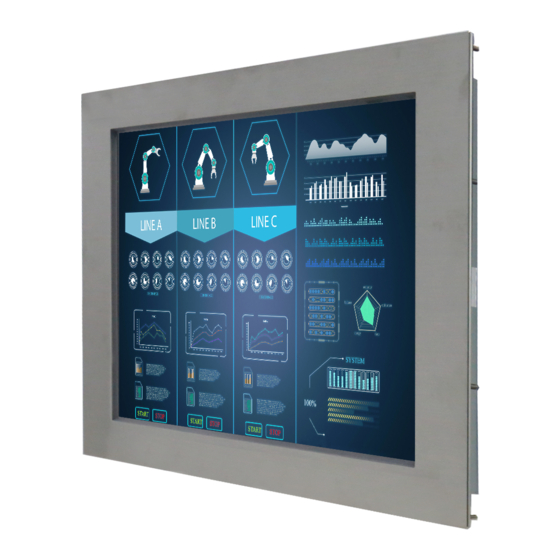
- Page 1 Full IP67 Chassis Display 10.4/ 15/ 19” User Manual Version 1.0 Document Part Number: 91521110103U Please read these instructions carefully before using this product, and save this manual for future use.
-
Page 2: Table Of Contents
Full IP67 Chassis Display User Manual Contents Preface About This User Manual Chapter 1: Introduction 1.1 Overview ......................9 1.2 Product Features ....................9 1.3 Package Contents ....................9 1.4 Product Overview ....................10 1.5 Physical Buttons and LED Indicators ..............12 1.6 Connectors ...................... -
Page 3: Preface
Preface Preface Copyright Notice No part of this document may be reproduced, copied, translated, or transmitted in any form or by any means, electronic or mechanical, for any purpose, without the prior written permission of the original manufacturer. Trademark Acknowledgement Brand and product names are trademarks or registered trademarks of their respective owners. - Page 4 Full IP67 Chassis Display User Manual Naming Rule R10L100-67XXXX Item Description Panel Type Panel Size LXXX Panel Specifications Mechanical Type (Full IP67) XXXX Panel Model Advisory Conventions Four types of advisories are used throughout the user manual to provide helpful information or to alert you to the potential for hardware damage or personal injury.
- Page 5 Preface Safety Information Warning!/ Avertissement! Always completely disconnect the power cord from your chassis whenever you work with the hardware. Do not make connections while the power is on. Sensitive electronic components can be damaged by sudden power surges. Only experienced electronics personnel should open the PC chassis.
- Page 6 Full IP67 Chassis Display User Manual Safety Precautions For your safety carefully read all the safety instructions before using the device. Keep this user manual for future reference. Always disconnect this equipment from any AC outlet before cleaning. Do not use liquid or spray detergents for cleaning.
-
Page 7: About This User Manual
About This User Manual About This User Manual This User Manual provides information about using the Winmate® Full IP67 Chassis Display. The documentation set provides information for specific user needs, and includes: Full IP67 Chassis Display User Manual – contains detailed description on how to use the display, its components and features. -
Page 8: Chapter 1: Introduction
Full IP67 Chassis Display User Manual Chapter 1: Introduction This chapter gives you product overview, describes features and hardware specification. You will find all accessories that come with the display device in the packing list. Mechanical dimensions and drawings included in this chapter. -
Page 9: Overview
Chapter 1: Introduction 1.1 Overview Congratulations on purchasing Winmate® Full IP67 Chassis Display. Winmate multipurpose and waterproof fully sealed IP67 display is protected against outer dust and water splash, and ideal for use in harsh environments such as food processing and packaging automation. food processing and packaging automation. -
Page 10: Product Overview
This section describes physical appearance of the Full IP67 Chassis Display. Notice that input and output connectors vary by product size and specifications. The picture above shows only a prototype model for information purposes only. 10.4-inch, R10L100-67T2ST Unit:mm 15-inch, R15L600-67C3ST... - Page 11 Chapter 1: Introduction 19-inch, R19L300-67M1ST Unit:mm...
-
Page 12: Physical Buttons And Led Indicators
Full IP67 Chassis Display User Manual 1.5 Physical Buttons and LED Indicators Physical buttons and LED indicators located on the rear side of the Display. Physical Buttons Icon Button Description DOWN/ Press to decrease the volume or VOLUME volume down when without OSD DOWN menu. -
Page 13: Connectors
Chapter 1: Introduction 1.6 Connectors Full IP67 Chassis Display has M25 type connectors with protection caps. Caution/ Attention To maintain device’s IP67 rating close the I/O and tighten protection caps when I/O is not used. Pour maintenir la norme IP67 de l'appareil près d'E / S et serrer capuchons de protection lorsque E / S est pas utilisé. -
Page 14: Chapter 2: Installation
Full IP67 Chassis Display User Manual Chapter 2: Installation This chapter provides hardware installation instructions and mounting guide for all available mounting options. Pay attention to cautions and warning to avoid any damages... -
Page 15: Wiring Requirements
Chapter 2: Installation 2.1 Wiring Requirements The following common safety precautions should be observed before installing any electronic device: Strive to use separate, non-intersecting paths to route power and networking wires. If power wiring and device wiring paths must cross make sure the wires are perpendicular at the intersection point. -
Page 16: Vesa Mount
100 x 100 mm VESA M4, D=5 mm Installation Instruction: 1. Screw VESA bracket to the fixture (ex. swing arm) with four VESA screws. 2. Place the device on VESA bracket. Notice that VESA stand and mounting kit are not provided by Winmate. -
Page 17: Yoke Mount
2. Secure screws to fix the device upon the bracket stand. 3. Firmly secure the locking handle to the Display. Notice that bracket stand is not provided by Winmate. 2.3 Cable Mounting Considerations For a nice look and safe installation, make sure cables are neatly hidden behind the device. -
Page 18: Connecting Power
Full IP67 Chassis Display User Manual 2.4 Connecting Power This section provides information on how to use connectors on the Display. Be cautious while working with these modules. Please carefully read the content of this chapter in order to avoid any damages. -
Page 19: Connecting Peripherals
Chapter 2: Installation 2.5 Connecting Peripherals The panel control port is designed for monitors that work with a variety of compatible video sources. Due to the possible deviations between these signal sources, you may have to make adjustments to the monitor settings from the OSD menu when switching between these sources. Note: Notice that standard input terminals include VGA. -
Page 20: Usb Cable For Touch
Full IP67 Chassis Display User Manual 2.5.2 USB Cable for Touch The display may have optional M25 type USB connector for touch based on your order. Use USB cable to connect touch. 2.5.3 RS-232 Cable for Touch The display may have optional M25 type serial port connector based on your order. Use serial cable to connect touch. -
Page 21: Vga Cable
Chapter 2: Installation 2.5.4 VGA Cable The display has M25 type VGA connector. Use VGA cable to connect the display to other external devices. 2.5.5 DVI Cable The display may have optional DVI connector based on your order. Use DVI cable to connect the display to other external device. -
Page 22: Chapter 3: Operating The Device
Full IP67 Chassis Display User Manual Chapter 3: Operating the Device In this chapter you will find instructions on how to operate the display. -
Page 23: Turning On And Off The Device
Chapter 3: Operating the Device 3.1 Turning On and Off the Device To turn on the system: 1. Connect the power adapter cable to the DC input of the display. 2. Connect the power cord to the power adapter. 3. Connect the power cord to a power outlet. 4. -
Page 24: Osd Menu Navigation
Full IP67 Chassis Display User Manual 3.2 OSD Menu Navigation OSD Icon Sub-menu Settings Note BRIGHTNESS slider bar Default 50 Use to adjust the screen’s brightness. Range 0 to 100 CONTRAST slider bar Default 50 BRICONTRAST Use to adjust the screen’s contrast. Range 0 to 100 H POSITION slider bar Default 50... -
Page 25: Troubleshooting Guide
Chapter 3: Operating the Device 3.3 Troubleshooting Guide If your monitor fails to operate correctly, check the following chart for possible solution before calling for repairs: Condition Check Point • Check if the signal cable is firmly seated in the socket. The picture does not •... -
Page 26: Appendix
Full IP67 Chassis Display User Manual Appendix This chapter contains additional product information, including troubleshooting guide and frequency table... -
Page 27: Appendix A: Frequency Table
Appendix Appendix A: Frequency Table The choice of supported modes depends on the monitor native resolution. Refer to the table below for more information about available input signals. Signal name Vertical Frequency (Hz) ✔ ✔ ✔ ✔ 640 x 480 ✔... - Page 28 Winmate Inc. 9F, No.111-6, Shing-De Rd., San-Chung District, New Taipei City 24158, Taiwan, R.O.C www.winmate.com Copyright © Winmate Inc. All rights reserved.
Need help?
Do you have a question about the R10L100-67T2ST and is the answer not in the manual?
Questions and answers