
Subscribe to Our Youtube Channel
Related Manuals for Microchip Technology MIC23656


Summary of Contents for Microchip Technology MIC23656
- Page 1 MIC23656 Evaluation Board User’s Guide 2018 Microchip Technology Inc. DS50002815A...
- Page 2 WiperLock, Wireless DNA, and ZENA are trademarks of Microchip Technology Incorporated in the U.S.A. and other countries. SQTP is a service mark of Microchip Technology Incorporated in Microchip received ISO/TS-16949:2009 certification for its worldwide headquarters, design and wafer fabrication facilities in Chandler and the U.S.A.
-
Page 3: Table Of Contents
1.1 Introduction ..................... 7 1.2 MIC23656 Short Overview ................7 1.3 What is the MIC23656 Evaluation Board? ............. 8 1.4 Contents of the MIC23656 Evaluation Board Kit ..........8 Chapter 2. Installation and Operation 2.1 Introduction ..................... 9 2.2 Features ....................... 10 2.3 Getting Started ..................... -
Page 4: Preface
• Customer Support • Document Revision History DOCUMENT LAYOUT This document describes how to use the MIC23656 Evaluation Board as a development tool. The manual layout is as follows: • Chapter 1. “Product Overview” – Important information about the MIC23656. -
Page 5: Conventions Used In This Guide
Curly brackets and pipe Choice of mutually exclusive errorlevel {0|1} character: { | } arguments; an OR selection Ellipses... Replaces repeated text var_name [, var_name...] Represents code supplied by void main (void) user { ... 2018 Microchip Technology Inc. DS50002815A-page 5... -
Page 6: Recommended Reading
Preface RECOMMENDED READING This user's guide describes how to use the MIC23656 Evaluation Board. Another useful document is listed below. The following Microchip document is available and recommended as a supplemental reference resource: • MIC23656 Data Sheet - “6A, Step-Down Converter with HyperLight Load™... -
Page 7: Chapter 1. Product Overview
An open-drain Power Good (PG) output is provided to indicate when the output voltage is within 9% of regulation and facilitates output voltage monitoring and sequencing. When set in Shutdown mode (EN = GND), the current consumption of MIC23656 is reduced to 1.5 µA (typical). -
Page 8: What Is The Mic23656 Evaluation Board
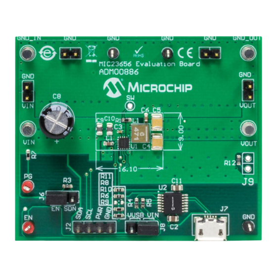
Product Overview WHAT IS THE MIC23656 EVALUATION BOARD? The MIC23656 Evaluation Board is used to evaluate and demonstrate Microchip Technology’s MIC23656 product. This board demonstrates the MIC23656 in a buck converter application supplied from an external voltage source (2.4V-5.5V), with I programmed regulated output. -
Page 9: Chapter 2. Installation And Operation
USER’S GUIDE Chapter 2. Installation and Operation INTRODUCTION The MIC23656 Evaluation Board has been developed to test the MIC23656 capabilities, including loading up to 6A, control and monitor through the USB interface (via I C Monitor GUI). Pin headers are also fitted for Bode Analysis and external I communication. -
Page 10: Features
The MIC23656 Evaluation Board is fully assembled and tested to evaluate and demonstrate the MIC23656 product. This board requires the use of external lab supplies and a PC. The MIC23656 is offered in four different product options, depend- ing on the default settings at power-up, prior to any I C write operation. - Page 11 The inductance associated with long wires on the board input may cause voltage spikes at load stepping or start-up into heavy load. If the spikes exceed the 5.5V maximum input voltage rating, the MIC23656 may fail. This can be prevented by populating a 470 F Electrolytic Capacitor on C8 µ...
- Page 12 2.3.1.4 LOOP GAIN MEASUREMENT The MIC23656 Evaluation Board provides injection points and a termination resistor (R4) for AC loop gain measurements. If needed, the value of R4 can be changed to optimize the injection signal level. Inject the oscillator at J6 through the insulation trans- former (i.e., across resistor R4) and connect the A (CH1) and B (CH2) channels to TP1...
- Page 13 1 of register CTRL1 (address 0x00) set to ‘1’, the MIC23656 is enabled. By placing a jumper on the SDN posi- tion, the MIC23656 is disabled. The MIC23656 Evaluation Board features a pull-down resistor R3 connected to the EN pin, so, by default, without any jumper connected, the regulator will be disabled.
- Page 14 First, the input and output capacitors should be placed as close to the MIC23656 as possible and on the same layer as the IC. This will ensure low ripple and lower switching noise. Then, vias must be used under the MIC23656, from its exposed pad to the GND plane, in order to improve heat dissipation.
-
Page 15: Chapter 3. Gui Installation And Operation
• Microsoft .NET Framework 4.5 or higher • Adobe Acrobat Reader 3.1.2 Required Hardware • MIC23656 Evaluation Board • USB-to-micro-USB Cable GRAPHICAL USER INTERFACE INSTALLATION The following steps describe how to install the I C Monitor Graphical User Interface: ®... - Page 16 Starting the I C Monitor Graphical User Interface Installation. 7. The installation path can be changed, although it is recommended to keep the default path. Click Next to continue. FIGURE 3-2: Selecting the Destination Folder. 2018 Microchip Technology Inc. DS50002815A-page 16...
- Page 17 8. In the Ready to Install the Program window, click the Install button and wait for the application to proceed with the installation. The progress can be observed in the “Status” bar. FIGURE 3-3: Installing the I C Monitor Graphical User Interface. 2018 Microchip Technology Inc. DS50002815A-page 17...
-
Page 18: I 2 C Monitor Graphical User Interface Uninstall
To uninstall, go to Windows Start>Control Panel>Uninstall a program>I2CMonitor. The C Monitor GUI will automatically close once the uninstallation process is complete. FIGURE 3-5: Uninstalling the I C Monitor Graphical User Interface. 2018 Microchip Technology Inc. DS50002815A-page 18... -
Page 19: Chapter 4. Gui Description
C Generic Register View MIC23656 I Programmable Features MIC23656 Status Bar MIC23656 I Progress Bar Diagnostic Control by MCP2221 GP0 output FIGURE 4-1: C Monitor Graphical User Interface Main Window - MIC23656 View. 2018 Microchip Technology Inc. DS50002815A-page 19... -
Page 20: The Graphical User Interface
“Board” descriptor and select the desired “Device” profile. FIGURE 4-3: Custom Board Menu. 4.2.4 C Monitor Status and Control Bar The “Status and Control” bar contains the items in Table 4-1. FIGURE 4-4: C Monitor Status and Control Bar. 2018 Microchip Technology Inc. DS50002815A-page 20... - Page 21 Register area This section shows the current status of the registers address and their content. The specific registers for MIC23656 are described in Appendix C. “MIC23656 Inter- nal Registers”. 2018 Microchip Technology Inc. DS50002815A-page 21...
- Page 22 The MIC23656 I C “Programmable Features” area contains the items in Table 4-3. FIGURE 4-6: MIC23656 I C Programmable Features Area (Low Range). FIGURE 4-7: MIC23656 I C Programmable Features Area (High Range). 2018 Microchip Technology Inc. DS50002815A-page 22...
- Page 23 MCP2221 GP0. Enable Bit This check box sets the MIC23656 enable bit register. Check the box for regulator enabling, uncheck for disabling. This bit value is considered only if EN Pin/Bit Enable Control is checked.
- Page 24 This box is checked if the regulator output is latched off, due to four consecutive hiccup events or thermal shutdown. OverTemp Shutdown This box is checked if the MIC23656 enters Thermal Shutdown (Typ. T = +165°C) Current Limit This box is checked if the high-side sensed current reaches the value set in the “Current Limit”...
- Page 25 STATUS LABELS Status Label Description STATUS: Connected! This message is shown when the GUI connects to a device. STATUS: Disconnected! This message is shown when the GUI does not detect a connected device. 2018 Microchip Technology Inc. DS50002815A-page 25...
-
Page 26: Appendix A. Schematic And Layouts
MIC23656 EVALUATION BOARD USER’S GUIDE Appendix A. Schematic and Layouts INTRODUCTION This appendix contains the following schematic and layouts for the MIC23656 Evaluation Board: • Board – Schematic • Board – Top Silk • Board – Top Copper and Silk •... -
Page 27: Board - Schematic
BOARD – SCHEMATIC Shunt 2.54mm 1x2 HDR-2.54 Male 1x3 4.7uF 4.7uF USB2.0 Micro-B Female UART RX UART RX 0805 0805 UART TX UART TX MCP2221A 49.9R 0603 470nH 0603 22uF 22uF 47uF 47uF 0.1uF 470uF 0.1uF TP LOOP Red 0805 0805 1210 1210... -
Page 28: Board - Top Silk
Schematic and Layouts BOARD – TOP SILK BOARD – TOP COPPER AND SILK 2018 Microchip Technology Inc. DS50002815A-page 28... -
Page 29: Board - Top Copper
Schematic and Layouts BOARD – TOP COPPER BOARD – BOTTOM COPPER 2018 Microchip Technology Inc. DS50002815A-page 29... -
Page 30: Appendix B. Bill Of Materials (Bom)
Mechanical HW Rubber PAD, SJ61A11 PAD3, PAD4 Cylindrical, D7.9, H5.3, Black PCB1 MIC23656 Evaluation Board Microchip Technology Inc. 04-10746-R1 Printed Circuit Board ® Resistor, TKF, 49.9R, 1%, Panasonic - ECG ERJ-3EKF49R9V 1/10W, SMD, 0603 2018 Microchip Technology Inc. DS50002815A-page 30... - Page 31 ERJ-3GSY0R00V SMD, 0603 Resistor, TKF, 10R, 1%, Panasonic - ECG ERJ-3EKF10R0V 1/10W, SMD, 0603 Microchip Analog Switcher Microchip Technology, Inc. MIC23656-HAYFT Buck, 2.4V to 5.5V, MIC23656-HAYFT FTQFN-16 Microchip Interface USB I Microchip Technology, Inc. MCP2221-I/ST UART, MCP2221-I/ST, TSSOP-14 Note 1: The components listed in this Bill of Materials are representative of the PCB assembly.
-
Page 32: Appendix C. Mic23656 Internal Registers
MIC23656 EVALUATION BOARD USER’S GUIDE Appendix C. MIC23656 Internal Registers REGISTER MAP AND I C PROGRAMMABILITY Table C-1 The MIC23656 internal registers are summarized in TABLE C-1: MIC23656 REGISTER MAP Address Register Name 0x00 Control Register (CTRL1) TON<1:0> ILIM<1:0> EN_DELAY<1:0>... - Page 33 0101 = 1200 0110 = 1400 0111 = 1600 1000 = 1800 1001 = 2000 1010 = 2200 1011 = 2400 1100 = 2600 1101 = 2800 1110 = 3000 1111 = 3200 2018 Microchip Technology Inc. DS50002815A-page 33...
- Page 34 0xFD = 1.27V 0x7E = 0.635V 0x9E = 0.795V 0xBE = 0.955V 0xDE = 1.115V 0xFE = 1.275V 0x7F = 0.64V 0x9F = 0.8V 0xBF = 0.96V 0xDF = 1.12V 0xFF = 1.28V 2018 Microchip Technology Inc. DS50002815A-page 34...
- Page 35 0x5E = 0.95V 0x7E = 1.27V 0x9E = 1.9V 0xBE = 2.54V 0xDE = 3.18V 0xFE = 3.82V 0x3F = 0.64V 0x5F = 0.96V 0x7F = 1.28V 0x9F = 1.92V 0xBF = 2.56V 0xDF = 3.2V 0xFF = 3.84V 2018 Microchip Technology Inc. DS50002815A-page 35...
- Page 36 1 = Fault bit 1 LATCH_OFF: Overcurrent or Overtemperature Output Latch Off 0 = No Fault 1 = Fault bit 0 PG: Power Good 0 = Power Not Good 1 = Power Good 2018 Microchip Technology Inc. DS50002815A-page 36...
-
Page 37: Worldwide Sales And Service
New York, NY Tel: 46-31-704-60-40 Tel: 631-435-6000 Sweden - Stockholm San Jose, CA Tel: 46-8-5090-4654 Tel: 408-735-9110 UK - Wokingham Tel: 408-436-4270 Tel: 44-118-921-5800 Canada - Toronto Fax: 44-118-921-5820 Tel: 905-695-1980 Fax: 905-695-2078 2018 Microchip Technology Inc. DS50002815A-page 37 08/15/18...
Need help?
Do you have a question about the MIC23656 and is the answer not in the manual?
Questions and answers