
Related Manuals for Microchip Technology MIC23356


Summary of Contents for Microchip Technology MIC23356
- Page 1 MIC23356 Evaluation Board User’s Guide 2018 Microchip Technology Inc. DS50002834A Arrow.com. Downloaded from...
- Page 2 WiperLock, Wireless DNA, and ZENA are trademarks of Microchip Technology Incorporated in the U.S.A. and other countries. SQTP is a service mark of Microchip Technology Incorporated in Microchip received ISO/TS-16949:2009 certification for its worldwide headquarters, design and wafer fabrication facilities in Chandler and the U.S.A.
-
Page 3: Table Of Contents
1.1 Introduction ..................... 8 1.2 MIC23356 Short Overview ................8 1.3 What is the MIC23356 Evaluation Board? ............. 9 1.4 Contents of the MIC23356 Evaluation Board Kit ..........9 Chapter 2. Installation and Operation 2.1 Introduction ....................10 2.2 Features ....................... 11 2.3 Getting Started ..................... - Page 4 A.9 Board – Bottom Copper and Silk ..............32 A.10 Board – Bottom Silk ................... 32 Appendix B. Bill of Materials (BOM) Appendix C. MIC23356 Internal Registers C.1 Register MAP and I2C programmability ............35 Worldwide Sales and Service ..................40 ...
-
Page 5: Preface
• Customer Support • Document Revision History DOCUMENT LAYOUT This document describes how to use the MIC23356 Evaluation Board as a development tool. The manual layout is as follows: • Chapter 1. “Product Overview” – Important information about the MIC23356. -
Page 6: Conventions Used In This Guide
{ | } arguments; an OR selection Ellipses... Replaces repeated text var_name [, var_name...] Represents code supplied by void main (void) user { ... 2018 Microchip Technology Inc. DS50002834A-page 6 Arrow.com. Arrow.com. Arrow.com. Arrow.com. Arrow.com. Arrow.com. Downloaded from Downloaded from... -
Page 7: Recommended Reading
Preface RECOMMENDED READING This user’s guide describes how to use the MIC23356 Evaluation Board. Another useful document is listed below. The following Microchip document is available and recommended as a supplemental reference resource: • MIC23356 Data Sheet - “3A, Step-Down Converter with HyperLight Load™... -
Page 8: Chapter 1. Product Overview
When set in Shutdown mode (EN = GND), the current consumption of MIC23356 is reduced to 1.5 µA (typical). The MIC23356 is available in a thermally-efficient, 16-Lead 2.5 x 2.5 x 0.55 mm thin MLF package, with an operating junction temperature range from -40°C to +125°C. -
Page 9: What Is The Mic23356 Evaluation Board
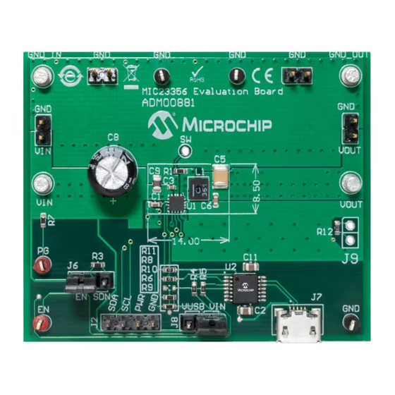
Product Overview WHAT IS THE MIC23356 EVALUATION BOARD? The MIC23356 Evaluation Board is used to evaluate and demonstrate Microchip Technology’s MIC23356 product. This board demonstrates the MIC23356 in a buck converter application supplied from an external voltage source (2.4V-5.5V), with I programmed regulated output. -
Page 10: Chapter 2. Installation And Operation
USER’S GUIDE Chapter 2. Installation and Operation INTRODUCTION The MIC23356 Evaluation Board has been developed to test the MIC23356 device’s capabilities, including loading up to 3A and controlling and monitoring through the USB interface (via I C Monitor GUI). Pin headers are also fitted for Bode Analysis and external I C communication. -
Page 11: Features
The MIC23356 Evaluation Board is fully assembled and tested to evaluate and demonstrate the MIC23356 product. This board requires the use of external lab supplies and a PC. The MIC23356 is offered in four different product options, depend- ing on the default settings at power-up, prior to any I C write operation. - Page 12 The inductance associated with long wires on the board input may cause voltage spikes at load stepping or start-up into heavy load. If the spikes exceed the 5.5V maximum input voltage rating, the MIC23356 may fail. This can be prevented by populating a 470 F Electrolytic Capacitor on C8 µ...
- Page 13 Installation and Operation 2.3.1.3 PERFORMANCE EVALUATION The Oscilloscope screen capture in Figure 2-3 displays the MIC23356 switching waveforms during normal operation, when supplied from 5V input at full load (3A). 5V/div 50 mV/div AC coupled 5V/div 5V/div FIGURE 2-3: Normal Operation at 0.6V Output, 3A Load.
- Page 14 (i.e., across resistor R12). 2.3.1.5 C PULL-UP VOLTAGE SELECTION The MIC23356 Evaluation Board is equipped with a jumper for selecting the I C pull-up supply voltage. The J8 header can be used to select the I C pull-up voltage to either or V .
- Page 15 First, the input and output capacitors should be placed as close to the MIC23356 as possible and on the same layer as the IC. This will ensure low ripple and lower switching noise. Then, vias must be used under the MIC23356, from its exposed pad to the GND plane, in order to improve heat dissipation.
-
Page 16: Chapter 3. Gui Installation And Operation
• Microsoft .NET Framework 4.5 or higher • Adobe Acrobat Reader 3.1.2 Required Hardware • MIC23356 Evaluation Board • USB-to-micro-USB Cable GRAPHICAL USER INTERFACE INSTALLATION The following steps describe how to install the I C Monitor Graphical User Interface: ®... - Page 17 C Monitor Graphical User Interface Installation. 7. The installation path can be changed, although it is recommended to keep the default path. Click Next to continue. FIGURE 3-2: Selecting the Destination Folder. 2018 Microchip Technology Inc. DS50002834A-page 17 Arrow.com. Arrow.com. Arrow.com.
- Page 18 8. In the Ready to Install the Program window, click the Install button and wait for the application to proceed with the installation. The progress can be observed in the “Status” bar. FIGURE 3-3: Installing the I C Monitor Graphical User Interface. 2018 Microchip Technology Inc. DS50002834A-page 18 Arrow.com. Arrow.com. Arrow.com. Arrow.com.
-
Page 19: C Monitor Graphical User Interface Uninstall
To uninstall, go to Windows Start>Control Panel>Uninstall a program>I2CMonitor. The C Monitor GUI will automatically close once the uninstallation process is complete. FIGURE 3-5: Uninstalling the I C Monitor Graphical User Interface. 2018 Microchip Technology Inc. DS50002834A-page 19 Arrow.com. Arrow.com. Arrow.com. -
Page 20: Chapter 4. Gui Description
Programmable Features MIC23356 Status Bar MIC23356 I Progress Bar Diagnostic Control by MCP2221 GP0 output FIGURE 4-1: C Monitor Graphical User Interface Main Window - MIC23356 View. 2018 Microchip Technology Inc. DS50002834A-page 20 Arrow.com. Arrow.com. Arrow.com. Arrow.com. Arrow.com. Arrow.com. -
Page 21: The Graphical User Interface
Custom Board Menu. 4.2.4 C Monitor Status and Control Bar The “Status and Control” bar contains the items in Table 4-1. FIGURE 4-4: C Monitor Status and Control Bar. 2018 Microchip Technology Inc. DS50002834A-page 21 Arrow.com. Arrow.com. Arrow.com. Arrow.com. Arrow.com. Arrow.com. -
Page 22: I2C Generic Register View
This button sets the number of available registers for read/write operations in the register area. Register area This section shows the current status of the registers address and their content. The specific registers for MIC23356 are described in Appendix C. “MIC23356 Internal Registers”. 2018 Microchip Technology Inc. -
Page 23: Mic23356 I2C Programmable Features
C “Programmable Features” area contains the items in Table 4-3. FIGURE 4-6: MIC23356 I C Programmable Features Area – Low Range. FIGURE 4-7: MIC23356 I C Programmable Features Area – High Range. 2018 Microchip Technology Inc. DS50002834A-page 23 Arrow.com. Arrow.com. Arrow.com. Arrow.com. Arrow.com. Arrow.com. Arrow.com. - Page 24 MCP2221 GP0. Enable Bit This check box sets the MIC23356 enable bit register. Check the box for regulator enabling, uncheck for disabling. This bit value is considered only if EN Pin/Bit Enable Control is checked.
-
Page 25: Mic23356 I2C Diagnostic
Latched Off This box is checked if the regulator output is latched off, due to four consecutive hiccup events or thermal shutdown. OverTemp This box is checked if the MIC23356 enters Thermal Shutdown Shutdown (Typ. T = +165°C) Current Limit This box is checked if the high-side sensed current reaches the value set in the “Current Limit”... - Page 26 Description STATUS: Connected! This message is shown when the GUI connects to a device. STATUS: Disconnected! This message is shown when the GUI does not detect a connected device. 2018 Microchip Technology Inc. DS50002834A-page 26 Arrow.com. Arrow.com. Arrow.com. Arrow.com.
-
Page 27: Appendix A. Schematic And Layouts
MIC23356 EVALUATION BOARD USER’S GUIDE Appendix A. Schematic and Layouts INTRODUCTION This appendix contains the following schematic and layouts for the MIC23356 Evaluation Board: • Board – Schematic • Board – Top Silk • Board – Top Copper and Silk •... - Page 28 MIC23356 Evaluation Board User’s Guide 2018 Microchip Technology Inc. DS50002834A-page 28 Arrow.com. Arrow.com. Arrow.com. Arrow.com. Arrow.com. Arrow.com. Arrow.com. Arrow.com. Arrow.com. Arrow.com. Arrow.com. Arrow.com. Arrow.com. Arrow.com. Arrow.com. Arrow.com. Arrow.com. Arrow.com. Arrow.com. Arrow.com. Arrow.com. Arrow.com. Arrow.com. Arrow.com. Arrow.com. Arrow.com. Arrow.com. Arrow.com.
-
Page 29: Board - Top Silk
Schematic and Layouts BOARD – TOP SILK BOARD – TOP COPPER AND SILK 2018 Microchip Technology Inc. DS50002834A-page 29 Arrow.com. Arrow.com. Arrow.com. Arrow.com. Arrow.com. Arrow.com. Arrow.com. Arrow.com. Arrow.com. Arrow.com. Arrow.com. Arrow.com. Arrow.com. Arrow.com. Arrow.com. Arrow.com. Arrow.com. Arrow.com. Arrow.com. Arrow.com. -
Page 30: Board - Top Copper
Schematic and Layouts BOARD – TOP COPPER BOARD – MIDDLE LAYER 1 2018 Microchip Technology Inc. DS50002834A-page 30 Arrow.com. Arrow.com. Arrow.com. Arrow.com. Arrow.com. Arrow.com. Arrow.com. Arrow.com. Arrow.com. Arrow.com. Arrow.com. Arrow.com. Arrow.com. Arrow.com. Arrow.com. Arrow.com. Arrow.com. Arrow.com. Arrow.com. Arrow.com. Arrow.com. -
Page 31: Board - Middle Layer 2
Schematic and Layouts BOARD – MIDDLE LAYER 2 BOARD – BOTTOM COPPER 2018 Microchip Technology Inc. DS50002834A-page 31 Arrow.com. Arrow.com. Arrow.com. Arrow.com. Arrow.com. Arrow.com. Arrow.com. Arrow.com. Arrow.com. Arrow.com. Arrow.com. Arrow.com. Arrow.com. Arrow.com. Arrow.com. Arrow.com. Arrow.com. Arrow.com. Arrow.com. Arrow.com. Arrow.com. -
Page 32: Board - Bottom Copper And Silk
Schematic and Layouts BOARD – BOTTOM COPPER AND SILK A.10 BOARD – BOTTOM SILK 2018 Microchip Technology Inc. DS50002834A-page 32 Arrow.com. Arrow.com. Arrow.com. Arrow.com. Arrow.com. Arrow.com. Arrow.com. Arrow.com. Arrow.com. Arrow.com. Arrow.com. Arrow.com. Arrow.com. Arrow.com. Arrow.com. Arrow.com. Arrow.com. Arrow.com. Arrow.com. -
Page 33: Appendix B. Bill Of Materials (Bom)
MIC23356 EVALUATION BOARD USER’S GUIDE Appendix B. Bill of Materials (BOM) TABLE B-1: MIC23356 EVALUATION BOARD – BILL OF MATERIALS (BOM) Qty. Reference Description Manufacturer Part Number Ceramic capacitor, 1 F, 16V, 10%, Yageo Corporation CC0603KRX7R7BB105 X7R, SMD, 0603 Ceramic capacitor, 4.7 F, 10V, 10%,... - Page 34 Bill of Materials (BOM) TABLE B-1: MIC23356 EVALUATION BOARD – BILL OF MATERIALS (BOM) (CONTINUED) Qty. Reference Description Manufacturer Part Number R4, R5, R8, R11 Resistor, TKF, 0R 1/10W, SMD, 0603 Panasonic - ECG ERJ-3GSY0R00V R6, R9 Resistor, TKF, 2 k 1%, 1/10W, SMD,...
-
Page 35: Appendix C. Mic23356 Internal Registers
MIC23356 EVALUATION BOARD USER’S GUIDE Appendix C. MIC23356 Internal Registers REGISTER MAP AND I C PROGRAMMABILITY Table C-1 The MIC23356 internal registers are summarized in TABLE C-1: MIC23356 REGISTER MAP Address Register Name 0x00 Control Register (CTRL1) TON<1:0> Reserved ILIM EN_DELAY<1:0>... - Page 36 0111 = 1600 1000 = 1800 1001 = 2000 1010 = 2200 1011 = 2400 1100 = 2600 1101 = 2800 1110 = 3000 1111 = 3200 2018 Microchip Technology Inc. DS50002834A-page 36 Arrow.com. Arrow.com. Arrow.com. Arrow.com. Arrow.com. Arrow.com. Arrow.com.
- Page 37 0x9E = 0.795V 0xBE = 0.955V 0xDE = 1.115V 0xFE = 1.275V 0x7F = 0.64V 0x9F = 0.8V 0xBF = 0.96V 0xDF = 1.12V 0xFF = 1.28V 2018 Microchip Technology Inc. DS50002834A-page 37 Arrow.com. Arrow.com. Arrow.com. Arrow.com. Arrow.com. Arrow.com. Arrow.com.
- Page 38 0xBE = 2.54V 0xDE = 3.18V 0xFE = 3.82V 0x3F = 0.64V 0x5F = 0.96V 0x7F = 1.28V 0x9F = 1.92V 0xBF = 2.56V 0xDF = 3.2V 0xFF = 3.84V 2018 Microchip Technology Inc. DS50002834A-page 38 Arrow.com. Arrow.com. Arrow.com. Arrow.com.
- Page 39 LATCH_OFF: Overcurrent or Overtemperature Output Latch Off bit 0 = No Fault 1 = Fault bit 0 PG: Power Good bit 0 = Power Not Good 1 = Power Good 2018 Microchip Technology Inc. DS50002834A-page 39 Arrow.com. Arrow.com. Arrow.com. Arrow.com. Arrow.com.
-
Page 40: Worldwide Sales And Service
Sweden - Stockholm San Jose, CA Tel: 46-8-5090-4654 Tel: 408-735-9110 UK - Wokingham Tel: 408-436-4270 Tel: 44-118-921-5800 Canada - Toronto Fax: 44-118-921-5820 Tel: 905-695-1980 Fax: 905-695-2078 2018 Microchip Technology Inc. DS50002834A-page 40 08/15/18 Arrow.com. Arrow.com. Arrow.com. Arrow.com. Arrow.com. Arrow.com. Arrow.com. Arrow.com.
Need help?
Do you have a question about the MIC23356 and is the answer not in the manual?
Questions and answers