
Related Manuals for Microchip Technology MIC33M356


Summary of Contents for Microchip Technology MIC33M356
- Page 1 MIC33M356 Evaluation Board User’s Guide 2020 Microchip Technology Inc. DS50002987A...
- Page 2 Technology, and Symmcom are registered trademarks of Microchip Technology Inc. in other countries. GestIC is a registered trademark of Microchip Technology Germany II GmbH & Co. KG, a subsidiary of Microchip Technology Inc., in other countries. All other trademarks mentioned herein are property of their respective companies.
-
Page 3: Table Of Contents
1.1 Introduction ..................... 9 1.2 MIC33M356 Short Overview ................9 1.3 What is the MIC33M356 Evaluation Board? ..........10 1.4 Contents of the MIC33M356 Evaluation Board Kit ........10 Chapter 2. Installation and Operation ................ 11 2.1 Introduction ....................11 2.2 Features ....................... - Page 4 MIC33M356 Evaluation Board User’s Guide Appendix B. Bill of Materials (BOM) ................35 Appendix C. MIC33M356 Internal Registers...............37 C.1 Register Map and I C Programmability ............37 Worldwide Sales and Service ..................42 2020 Microchip Technology Inc. DS50002987A-page 4...
-
Page 5: Preface
• Customer Support • Document Revision History DOCUMENT LAYOUT This document describes how to use the MIC33M356 Evaluation Board as a development tool. The manual layout is as follows: • Chapter 1. “Product Overview” – Important information about the MIC33M356. -
Page 6: Conventions Used In This Guide
MIC33M356 Evaluation Board User’s Guide CONVENTIONS USED IN THIS GUIDE This manual uses the following documentation conventions: DOCUMENTATION CONVENTIONS Description Represents Examples Arial font: ® Italic characters Referenced books MPLAB IDE User’s Guide Emphasized text ...is the only compiler... Initial caps... -
Page 7: Recommended Reading
Preface RECOMMENDED READING This user’s guide describes how to use the MIC33M356 Evaluation Board. Another useful document is the following Microchip document listed below, which is available and recommended as a supplemental reference resource: • MIC33M356 Data Sheet – “3A, Power Module Converter with HyperLight ®... - Page 8 MIC33M356 Evaluation Board User’s Guide NOTES: 2020 Microchip Technology Inc. DS50002987A-page 8...
-
Page 9: Chapter 1. Product Overview
When set in Shutdown mode (EN = GND), the MIC33M356 typically draws 1.5 µA. The MIC33M356 is available in a thermally efficient, 24-Lead, 3 mm x 4.5 mm x 1.8 mm QFN package, with an operating junction temperature range from -40°C to +125°C. -
Page 10: What Is The Mic33M356 Evaluation Board
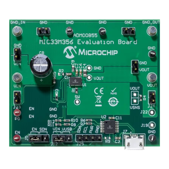
MIC33M356 Evaluation Board User’s Guide WHAT IS THE MIC33M356 EVALUATION BOARD? The MIC33M356 Evaluation Board is used to evaluate and demonstrate Microchip Technology’s MIC33M356 module. This board demonstrates the MIC33M356 in a buck converter application supplied from an external voltage source (2.4V-5.5V), with I programmed regulated output. -
Page 11: Chapter 2. Installation And Operation
USER’S GUIDE Chapter 2. Installation and Operation INTRODUCTION The MIC33M356 Evaluation Board has been developed to test the MIC33M356 capabilities, including loading up to a 3A control and monitor through the USB interface (via I C monitor GUI). Pin headers are also fitted for Bode analysis and external I communication. -
Page 12: Features
The MIC33M356 Evaluation Board is fully assembled and tested to evaluate and demonstrate the MIC33M356 module. This board requires the use of external lab supplies and a PC. The MIC33M356 is offered in four different product options, depending on the default settings at power-up, prior to any I C write operation. - Page 13 Power Supply Voltmeter Load Ammeter (10A) C Monitor (PC) Oscilloscope FIGURE 2-2: MIC33M356 Evaluation Board Test Setup. 2020 Microchip Technology Inc. DS50002987A-page 13...
- Page 14 2.3.1.5 C PULL-UP VOLTAGE SELECTION The MIC33M356 Evaluation Board is equipped with a jumper for selecting the I pull-up supply voltage. The J12 header can be used to select the I C pull-up voltage to...
- Page 15 EN jumper on J5, EN position (or by applying a logic ‘1’ voltage on the EN test point). The MIC33M356 does not retain the set voltage and returns to the default configuration after a power cycle.
- Page 16 MIC33M356 Evaluation Board User’s Guide NOTES: 2020 Microchip Technology Inc. DS50002987A-page 16...
-
Page 17: Chapter 3. Gui Installation And Operation
• Adobe Acrobat Reader 3.1.2 Required Hardware • MIC33M356 Evaluation Board • USB to Micro-USB Cable GRAPHICAL USER INTERFACE INSTALLATION The following steps describe how to install the I C Monitor Graphical User Interface: 1. If Microsoft.NET Framework is already installed, go to Step 3. - Page 18 MIC33M356 Evaluation Board User’s Guide 6. In the Welcome to the InstallShield Wizard for I2CMonitor window, click the Next button to start the installation. FIGURE 3-1: Starting the I C Monitor Graphical User Interface Installation. 7. The installation path can be changed, although it is recommended to keep the default path.
- Page 19 8. In the Ready to Install the Program window, click the Install button and wait for the application to proceed with the installation. The progress can be observed in the “Status” bar. FIGURE 3-3: Installing the I C Monitor Graphical User Interface. 2020 Microchip Technology Inc. DS50002987A-page 19...
-
Page 20: I 2 C Monitor Graphical User Interface Uninstall
MIC33M356 Evaluation Board User’s Guide 9. Once the installation is complete, leave the “Launch the program” box checked to automatically start the I C Monitor GUI, or deselect this check box to start the GUI at a later stage. Click Finish to end the installation. -
Page 21: Chapter 4. Gui Description
C Generic Register View MIC33M356 I Programmable Features MIC33M356 MIC33M356 I Control by MCP2221 GP0 Output Status Bar Diagnostic Progress Bar FIGURE 4-1: C Monitor Graphical User Interface Main Window – MIC33M356 View. 2020 Microchip Technology Inc. DS50002987A-page 21... -
Page 22: The Graphical User Interface
MIC33M356 Evaluation Board User’s Guide THE GRAPHICAL USER INTERFACE The following sections describe the items in the Graphical User Interface. 4.2.1 Device Menu The Device drop-down menu allows the user to select the device to be evaluated. If an evaluation (or added custom) board is used, the profile will automatically change to the preselected profile. - Page 23 Analyzer. Note: Optional. PICkit Serial Analyzer should first be connected on the I C pin header, on the MIC33M356 Evaluation Board. In the “Status and Control” bar, the user can choose the hardware tool for the communication with the device and the settings it should allow.
- Page 24 MIC33M356 Evaluation Board User’s Guide The specific registers for MIC33M356 are described in Appendix C. “MIC33M356 Internal Registers”. 4.2.6 MIC33M356 I C Programmable Features The MIC33M356 I C “Programmable Features” area contains the items in Table 4-3. FIGURE 4-6: MIC33M356 I C Programmable Features Area.
- Page 25 MCP2221 GP0. Enable Bit This check box sets the MIC33M356 Enable Bit register. Check the box for regulator enabling, uncheck for disabling. This bit value is considered only if EN Pin/Bit Enable Control is checked.
- Page 26 MIC33M356 Evaluation Board User’s Guide 4.2.7 MIC33M356 I C Diagnostic The MIC33M356 Diagnostic area contains the items in Table 4-4. FIGURE 4-7: MIC33M356 I C Diagnostic Area. TABLE 4-4: MIC33M356 I C DIAGNOSTIC AREA ITEMS Panel Items Description Status Power Good This box is checked if the output voltage reaches 91% of its set value.
- Page 27 STATUS LABELS Status Label Description STATUS: Connected! This message is shown when the GUI connects to a device. STATUS: Disconnected! This message is shown when the GUI does not detect a connected device. 2020 Microchip Technology Inc. DS50002987A-page 27...
- Page 28 MIC33M356 Evaluation Board User’s Guide NOTES: 2020 Microchip Technology Inc. DS50002987A-page 28...
-
Page 29: Appendix A. Schematic And Layouts
MIC33M356 EVALUATION BOARD USER’S GUIDE Appendix A. Schematic and Layouts INTRODUCTION This appendix contains the following schematic and layouts for the MIC33M356 Evaluation Board: • Board – Schematic • Board – Top Silk • Board – Top Copper and Silk •... -
Page 30: Board - Schematic
49.9R 0603 0603 UART TX 0603 0603 VOUT_TP MCP2221A 0.1 μF 47 μF GND_TP 0603 0603 0805 0.1% PGND PGND 0603 PGND 0.1% PGND 0603 PGND EP1_PGND AGND HDR-2.54 Male 1x2 MIC33M356 100k 0603 TP LOOP Red TP LOOP Black... -
Page 31: Board - Top Silk
Schematic and Layouts BOARD – TOP SILK BOARD – TOP COPPER AND SILK 2020 Microchip Technology Inc. DS50002987A-page 31... -
Page 32: Board - Top Copper
MIC33M356 Evaluation Board User’s Guide BOARD – TOP COPPER BOARD – SIGNAL LAYER 1 2020 Microchip Technology Inc. DS50002987A-page 32... -
Page 33: Board - Signal Layer 2
Schematic and Layouts BOARD – SIGNAL LAYER 2 BOARD – BOTTOM COPPER 2020 Microchip Technology Inc. DS50002987A-page 33... -
Page 34: Board - Bottom Copper And Silk
MIC33M356 Evaluation Board User’s Guide BOARD – BOTTOM COPPER AND SILK A.10 BOARD – BOTTOM SILK 2020 Microchip Technology Inc. DS50002987A-page 34... -
Page 35: Mic33M356 Evaluation Board User's Guide
70006431483 PAD3, PAD4 Rubber Pad, Cylindrical, D7.9, H5.3, Black PCB1 MIC33M356 Evaluation Board – Microchip Technology Inc. 04-10704-R1 Printed Circuit Board Note 1: The components listed in this Bill of Materials are representative of the PCB assembly. The released BOM used in manufacturing uses all RoHS-compliant components. - Page 36 MIC33M356 Evaluation Board User’s Guide TABLE B-1: BILL OF MATERIALS (BOM) (CONTINUED) Qty. Reference Description Manufacturer Part Number ® Resistor, TKF, 49.9R,1%, 1/10W, Panasonic ERJ3EKF49R9V SMD, 0603 Resistor, TKF, 10R, 1%, 1/10W, Panasonic ERJ3EKF10R0V SMD, 0603 DO NOT POPULATE Resistor, TKF, 1M, 1%, 1/10W,...
-
Page 37: Appendix C. Mic33M356 Internal Registers
MIC33M356 EVALUATION BOARD USER’S GUIDE Appendix C. MIC33M356 Internal Registers REGISTER MAP AND I C PROGRAMMABILITY Table C-1 The MIC33M356 internal registers are summarized in TABLE C-1: MIC33M356 REGISTER MAP Address Register Name 0x00 Output Control Register 1 (CTRL1) TON[1:0]... - Page 38 MIC33M356 Evaluation Board User’s Guide REGISTER C-2: CTRL2: OUTPUT CONTROL REGISTER 2 (ADDRESS 0x01) R/W-0 R/W-0 R/W-0 R/W-0 R/W-0 R/W-0 R/W-0 R/W-0 DIS_100PCT FPWM OT_LATCH PULLDN SLEW_RATE[3:0] bit 7 bit 0 Legend: R = Readable bit W = Writable bit U = Unimplemented bit, read as ‘0’...
- Page 39 0xFD = 1.27V 0x7E = 0.635V 0x9E = 0.795V 0xBE = 0.955V 0xDE = 1.115V 0xFE = 1.275V 0x7F = 0.64V 0x9F = 0.8V 0xBF = 0.96V 0xDF = 1.12V 0xFF = 1.28V 2020 Microchip Technology Inc. DS50002987A-page 39...
- Page 40 MIC33M356 Evaluation Board User’s Guide REGISTER C-3: VOUT: OUTPUT VOLTAGE CONTROL REGISTER (ADDRESS 0x02) bit 7-0 VO[7:0]: Output Voltage Control, Option: -SAYFT 0x00-0x3B = 0.6V 0x40 = 0.65V 0x60 = 0.97V 0x80 = 1.3V 0xA0 = 1.94V 0xC0 = 2.58V 0xE0 = 3.22V 0x41 = 0.66V...
- Page 41 1 = Fault bit 1 LATCH_OFF: Overcurrent or Overtemperature Output Latch Off 0 = No Fault 1 = Fault bit 0 PG: Power Good 0 = Power not good 1 = Power good 2020 Microchip Technology Inc. DS50002987A-page 41...
-
Page 42: Worldwide Sales And Service
New York, NY Tel: 46-31-704-60-40 Tel: 631-435-6000 Sweden - Stockholm San Jose, CA Tel: 46-8-5090-4654 Tel: 408-735-9110 UK - Wokingham Tel: 408-436-4270 Tel: 44-118-921-5800 Canada - Toronto Fax: 44-118-921-5820 Tel: 905-695-1980 Fax: 905-695-2078 2020 Microchip Technology Inc. DS50002987A-page 42 02/28/20...
Need help?
Do you have a question about the MIC33M356 and is the answer not in the manual?
Questions and answers