
Related Manuals for Microchip Technology MIC23350


Summary of Contents for Microchip Technology MIC23350
- Page 1 MIC23350 Evaluation Board User’s Guide 2018 Microchip Technology Inc. DS50002833A...
- Page 2 WiperLock, Wireless DNA, and ZENA are trademarks of Microchip Technology Incorporated in the U.S.A. and other countries. SQTP is a service mark of Microchip Technology Incorporated in Microchip received ISO/TS-16949:2009 certification for its worldwide headquarters, design and wafer fabrication facilities in Chandler and the U.S.A.
-
Page 3: Table Of Contents
1.1 Introduction ..................... 7 1.2 MIC23350 Device Short Overview ..............7 1.3 What is the MIC23350 Evaluation Board? ............. 8 1.4 Contents of the MIC23350 Evaluation Board Kit ..........8 Chapter 2. Installation and Operation 2.1 Introduction ..................... 9 2.2 Features ......................9 2.3 Getting Started ..................... -
Page 4: Preface
• Customer Support • Document Revision History DOCUMENT LAYOUT This document describes how to use the MIC23350 Evaluation Board as a development tool. The manual layout is as follows: • Chapter 1. “Product Overview” – Important information about the MIC23350 Evaluation Board. -
Page 5: Conventions Used In This Guide
Curly brackets and pipe Choice of mutually exclusive errorlevel {0|1} character: { | } arguments; an OR selection Ellipses... Replaces repeated text var_name [, var_name...] Represents code supplied by void main (void) user { ... 2018 Microchip Technology Inc. DS50002833A-page 5... -
Page 6: Recommended Reading
Preface RECOMMENDED READING This user’s guide describes how to use the MIC23350 Evaluation Board. Another useful document is listed below. The following Microchip document is available and recommended as a supplemental reference resource. • MIC23350 Data Sheet – “Step-Down Converter with Hyperlight Load™ and Voltage Select”... -
Page 7: Chapter 1. Product Overview
9% of regulation and facilitates output voltage monitoring and supply sequencing. When set in shutdown (EN = GND), the MIC23350 device draws a typical current of 1.5 µA. MIC23350 is available in a thermally efficient, 16-lead 2.5 mm x 2.5 mm x 0.55 mm thin FTQFN package, with an operating junction temperature range from -40°C to +125°C. -
Page 8: What Is The Mic23350 Evaluation Board
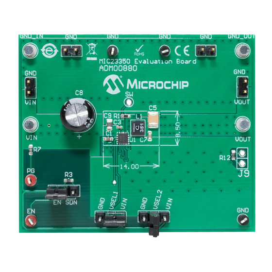
Product Overview WHAT IS THE MIC23350 EVALUATION BOARD? The MIC23350 Evaluation Board is used to evaluate and demonstrate the MIC23350 device. This board demonstrates the MIC23350 device in a buck converter application, supplied from an external voltage source (from 2.4V to 5.5V), to a pin-programmed regulated output. -
Page 9: Chapter 2. Installation And Operation
Chapter 2. Installation and Operation INTRODUCTION MIC23350 has been developed for applications suited for 2.4V to 5.5V input voltage range, low shutdown and quiescent currents, 3A continuous output current. This makes the MIC23350 device ideal for single cell Li-Ion battery-powered applications. The 100% duty cycle capability provides low-dropout operation, extending the operating range in portable systems. -
Page 10: Getting Started
Connect the positive voltage terminal of the load to the V terminal on the MIC23350 Evaluation Board and connect the negative or the return side of the load to the GND_OUT terminal. 2.3.1.2 BOARD POWER-UP PROCEDURE 1. - Page 11 FIGURE 2-2: MIC23350 Evaluation Board Setup. 2.3.1.3 ADJUSTING THE OUTPUT VOLTAGE There is no need for a resistor divided network on the MIC23350 device. The output voltage is simply selected before the power-up, through the V and V pins. SEL1...
- Page 12 5V/div 50 mV/div AC coupled 5V/div 5V/div FIGURE 2-3: Normal Operation at 0.6V Output, 3A Load. = 5.0V = 3.3V = 2.5V = 1V 0.001 0.01 FIGURE 2-4: Efficiency vs I at 1V. 2018 Microchip Technology Inc. DS50002833A-page 12...
- Page 13 First, the input and output capacitors should be placed as close to the MIC23350 device as possible, and on the same layer as the IC. This ensures low ripple and improved performance. Secondly, vias must be used under the MIC23350 device, from its exposed pad to the GND plane, in order to allow for best heat dissipation.
-
Page 14: Appendix A. Schematic And Layouts
MIC23350 EVALUATION BOARD USER’S GUIDE Appendix A. Schematic and Layouts INTRODUCTION This appendix contains the following schematics and layouts for the MIC23350 Evaluation Board: • Board – Schematic • Board – Top Silk • Board – Top Copper and Silk •... - Page 15 VSEL1 VSEL1 VSEL1 Shunt 2.54mm 1x2 Handle VSEL2 VSEL2 VSEL2 0603 HDR-2.54 Male 1x3 MIC23350 100k 0603 TP LOOP Red JP2 should be mounted on 1-2 pins J2 VSEL1 VSEL2 Shunt 2.54mm 1x2 Handle TP LOOP Black HDR-2.54 Male 1x3 HDR-2.54 Male 1x3...
-
Page 16: Board - Top Silk
Schematic and Layouts BOARD – TOP SILK BOARD – TOP COPPER AND SILK 2018 Microchip Technology Inc. DS50002833A-page 15... -
Page 17: Board - Top Copper
Schematic and Layouts BOARD – TOP COPPER BOARD – MID LAYER 1 2018 Microchip Technology Inc. DS50002833A-page 16... -
Page 18: Board - Bottom Copper
Schematic and Layouts BOARD – MID LAYER 2 BOARD – BOTTOM COPPER 2018 Microchip Technology Inc. DS50002833A-page 17... -
Page 19: Board - Bottom Copper And Silk
Schematic and Layouts BOARD – BOTTOM COPPER AND SILK A.10 BOARD – BOTTOM SILK 2018 Microchip Technology Inc. DS50002833A-page 18... -
Page 20: Appendix B. Bill Of Materials (Bom)
MIC23350 EVALUATION BOARD USER’S GUIDE Appendix B. Bill of Materials (BOM) TABLE B-1: MIC23350 EVALUATION BOARD – BILL OF MATERIALS (BOM) Qty. Reference Description Manufacturer Part Number Ceramic capacitor, 1 µF, 16V, 10%, Wurth Elektronik 885012206052 X7R, SMD, 0603 Ceramic capacitor, 0.1 µF, 16V, 10%,... - Page 21 Mechanical HW Rubber Pad, Cylindrical, SJ61A11 PAD3, PAD4 D7.9 H5.3, Black Note 1: The components listed in this Bill of Materials are representative of the PCB assembly. The released BOM used in manufacturing uses all RoHS-compliant components. 2018 Microchip Technology Inc. DS50002833A-page 20...
-
Page 22: Worldwide Sales And Service
New York, NY Tel: 46-31-704-60-40 Tel: 631-435-6000 Sweden - Stockholm San Jose, CA Tel: 46-8-5090-4654 Tel: 408-735-9110 UK - Wokingham Tel: 408-436-4270 Tel: 44-118-921-5800 Canada - Toronto Fax: 44-118-921-5820 Tel: 905-695-1980 Fax: 905-695-2078 2018 Microchip Technology Inc. DS50002833A-page 21 08/15/18...
Need help?
Do you have a question about the MIC23350 and is the answer not in the manual?
Questions and answers