
Related Manuals for BK Precision 4063


Summary of Contents for BK Precision 4063
- Page 1 Model: 4063, 4064, 4065 Function/Arbitrary Waveform Generator USER MANUAL GlobalTestSupply www. .com Find Quality Products Online at: sales@GlobalTestSupply.com...
-
Page 2: Safety Summary
Safety Summary The following safety precautions apply to both operating and maintenance personnel and must be followed during all phases of operation, service, and repair of this instrument. Before applying power to this instrument: Read and understand the safety and operational information in this manual. ... - Page 3 Do not use this instrument in an electrical environment with a higher category rating than what is specified in this manual for this instrument. You must ensure that each accessory you use with this instrument has a category rating equal to or higher than the instrument's category rating to maintain the instrument's category rating.
- Page 4 The instrument is designed to be used in office-type indoor environments. Do not operate the instrument In the presence of noxious, corrosive, or flammable fumes, gases, vapors, chemicals, or finely-divided particulates. In relative humidity conditions outside the instrument's specifications. ...
- Page 5 Do not clean the instrument, its switches, or its terminals with contact cleaners, abrasives, lubricants, solvents, acids/bases, or other such chemicals. Clean the instrument only with a clean dry lint-free cloth or as instructed in this manual. Not for critical applications This instrument is not authorized for use in contact with the human body or for use as a component in a life-support device or system.
- Page 6 This instrument contains one or more cooling fans. For continued safe operation of the instrument, the air inlet and exhaust openings for these fans must not be blocked nor must accumulated dust or other debris be allowed to reduce air flow. Maintain at least 25 mm clearance around the sides of the instrument that contain air inlet and exhaust ports.
-
Page 7: Compliance Statements
Compliance Statements Disposal of Old Electrical & Electronic Equipment (Applicable in the European Union and other European countries with separate collection systems) This product is subject to Directive 2002/96/EC of the European Parliament and the Council of the European Union on waste electrical and electronic equipment (WEEE), and in jurisdictions adopting that Directive, is marked as being put on the market after August 13, 2005, and should not be disposed of as unsorted... -
Page 8: Ce Declaration Of Conformity
CE Declaration of Conformity This instrument meets the requirements of 2006/95/EC Low Voltage Directive and 2004/108/EC Electromagnetic Compatibility Directive with the following standards. Low Voltage Directive EN61010-1: 2001 EMC Directive EN 61000-3-2: 2006 EN 61000-3-3: 1995+A1: 2001+A2: 2005 EN 61000-4-2 / -3 / -4 / -5 / -6 / -11 EN 61326-1: 2006 GlobalTestSupply www. -
Page 9: Safety Symbols
Safety Symbols Refer to the user manual for warning information to avoid hazard or personal injury and prevent damage to instrument. Electric Shock hazard Alternating current (AC) Chassis (earth ground) symbol. Ground terminal On (Power). This is the In position of the power switch when instrument is ON. -
Page 10: Table Of Contents
Contents Safety Summary ....................i Compliance Statements ......................vi Safety Symbols ........................viii General Information................1 Product Overview ......................1 Package Contents ......................1 Front Panel Overview ....................2 Front Panel Description ....................2 Rear Panel Overview ....................3 Rear Panel Description....................3 Display Overview ...................... - Page 11 Configure Arbitrary Waveform ................... 23 Configure Modulation Output ..................26 AM Modulation ......................26 FM Modulation ......................28 PM Modulation ......................29 FSK Modulation ......................31 ASK Modulation ......................32 DSB-AM ........................33 PWM Modulation (Pulse Only) ................... 34 Configure Sweep Output .................... 35 Configure Burst ......................
-
Page 12: General Information
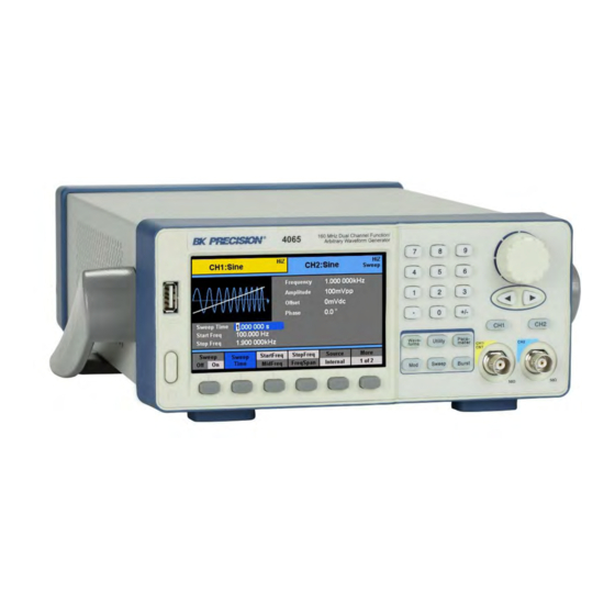
General Information 1.1 Product Overview The B&K Precision 4060 series are dual channel function / arbitrary waveform generators, capable of generating up to 160 MHz sine wave (model 4065). They have a large and informative easy-to-read color display, user-friendly controls, and a numeric keypad which allows users to easily configure waveform properties. -
Page 13: Front Panel Overview
1.3 Front Panel Overview Front Panel Description Power On/Off switch TFT LCD color display Menu function keys Waveforms/Utility/Parameter/Modulation/Sweep/Burst menu buttons Channel 1 output BNC/Counter input Channel 2 output BNC Channel 1 and 2 select buttons Arrow keys Rotary dial knob Numeric keypad USB host port/*USB-to-GPIB adapter interface Accepts USB flash drive to save/recall instrument settings and waveforms. -
Page 14: Rear Panel Overview
1.4 Rear Panel Overview Rear Panel Description External Trigger/Gate/FSK/Burst BNC connector 10MHz Out BNC connector USB interface AC input receptacle Chassis ground 10MHz In BNC connector Sync Output BNC Modulation Input BNC GlobalTestSupply www. .com Find Quality Products Online at: sales@GlobalTestSupply.com... -
Page 15: Display Overview
1.5 Display Overview Display Description Waveform display Menu options Waveform parameters display Waveform mode and output impedance indicator Selected channel indicator GlobalTestSupply www. .com Find Quality Products Online at: sales@GlobalTestSupply.com... -
Page 16: Getting Started
Getting Started Before connecting and powering up the instrument, please review and go through the instructions in this chapter. 2.1 Input Power Requirements Input Power The supply has a universal AC input that accepts line voltage and frequency input within: 100 –... -
Page 17: Impedance Matching
If there is a DC voltage across the output load, use a coupling capacitor in series with the load. The time constant of the coupling capacitor and load must be long enough to maintain pulse flatness. Impedance Matching If the waveform generator is driving a high impedance, such as a 1 MΩ input impedance (paralleled by a stated capacitance) of an oscilloscope vertical input, connect the transmission line to a 50 Ω... - Page 18 Press 7 to toggle through red, green, and blue colors. This test checks for dead pixels and color consistencies of the TFT LCD display. Press 8 to exit the test. KeyTest Select this option to do a key test. The screen will display a silhouette of buttons that represent the front panel buttons.
-
Page 19: Check Model And Firmware Version
start with the Waveforms button, which should light up. Its corresponding button in the silhouette should also turn blue. Continue to press 7 to toggle through all the buttons with backlights available. At the end of the test, all function, menu, and channel output buttons will light up, and all of their corresponding buttons in the silhouette on the display will turn blue. -
Page 20: Front Panel Operation
Waveform Shape: Sine Frequency: 1.000000 kHz Amplitude: 100 mVpp Offset: 0.0 mVdc Phase: 0.0 ° Output Impedance: Hi-Z 2. Connect the BNC output of CH1 (yellow) into an oscilloscope. 3. Press the Output button on top of CH1 output BNC to turn on the output and observe a sine wave with the parameters above. - Page 21 Waveforms Parameter Sine Frequency/Period Configures the frequency or period of the waveform. Amplitude/HighLevel Configures the amplitude or the high level of the waveform. Offset/LowLevel Configures the DC offset or the low level of the waveform. Phase Configures the phase relative to the other channel. Square Frequency/Period Configures the frequency or period of the waveform.
- Page 22 Sweep Sweep Time Configures the sweep time for sweep output. Configures the sweep start frequency or the center StartFreq/MidFreq frequency. Configures the sweep stop frequency or the frequency span StopFreq/FreqSpan of the sweep output. Source Selects the sweep source. Internal source: Selects to output a trigger signal at the start Trig Out of a sweep operation.
-
Page 23: Selecting A Channel
3.2 Selecting a Channel The 4060 series function/arbitrary waveform generators have dual channel outputs. They can be operated independently or in sync with each other. To select between channel 1 and 2 and view/change their parameters, toggle the keys. When Channel 1 is selected, the display will look like the following: When Channel 2 is selected, the display will look like the following: 3.3 Configure Waveform Output Configure Waveform Shape... - Page 24 Waveforms Sine Square Ramp Pulse Noise Arbitrary After the waveform selection, menu options relevant for that waveform shape will be shown on the bottom of the display. Below illustrates the screenshots shown when each of the waveform types is selected. Sine Waveform Square Waveform Ramp Waveform...
-
Page 25: Configure Frequency
Configure Frequency Note: This section does not apply for noise or DC waveform. Follow the steps below to configure the frequency or period of the output. The adjustable frequency range is different for each model and for each type of waveforms. See the specification section for the adjustable ranges. -
Page 26: Configure Dc Offset
4. After entering the numeric value, use the menu function keys to select the unit to apply for the amplitude setting. Available units are: Vpp, mVpp, Vrms, mVrms, and dBm (only available with 50 Ω output impedance). Note: Only using the numeric keypad will allow for changing the units from V to Vrms, mVrms, or dBm. -
Page 27: Configure Phase
1. From the menu, select Offset. 2. The cursor position will now highlight the first digit of the offset parameter display. 3. Use the rotary knob or the numeric keypad to change the offset. If numeric keypad is used, the following screen will be displayed: 4. -
Page 28: Configure Duty Cycle And Symmetry
Configure Duty Cycle and Symmetry Note: This section does not apply for sine, noise, DC, or arbitrary waveforms. Duty Cycle Note: For square and pulse waveforms only. Follow the steps below to configure the duty cycle of a square waveform. 1. - Page 29 Note: The adjustable duty cycle range varies depending on the frequency of the waveform. Some frequencies do not allow change or very little change of the duty cycle and can be fixed at 50%. Symmetry Note: For ramp waveform only. Follow the steps below to configure the symmetry of a ramp/triangle waveform.
-
Page 30: Configure Pulse Waveform
Configure Pulse Waveform Note: This section applies to pulse waveform only. Pulse Width and Pulse Duty Cycle The pulse width and duty cycle parameters are related and both control the length of the high level of the pulse. Users have the option to specify the pulse width in units of seconds or specify duty cycle as a percentage. -
Page 31: Configure Noise Waveform
4. Use the rotary knob or the numeric keypad to change the pulse delay. After entering the numeric value, use the menu function keys to select s, ms, us, or Rising or Falling Edge Follow the steps below to configure the rising or falling edge times. 1. - Page 32 Standard Deviation and Mean There are two parameters that can be adjusted of the noise waveform: Standard deviation and mean. Follow the steps below to configure these parameters. 1. Set the instrument for noise output. 2. From the menu, select Stdev for the standard deviation adjustment or Mean for the mean adjustment.
-
Page 33: Configure Dc Output Waveform
Configure DC Output Waveform The instrument can output a DC waveform output at a range of voltage levels (-12 Vdc – 12 Vdc). DC Offset There is only one parameter, DC Offset, to configure a DC output waveform. Follow the steps below to configure the parameter. 1. -
Page 34: Configure Arbitrary Waveform
Configure Arbitrary Waveform There are two ways to generate arbitrary waveforms. Users can output an arbitrary waveform selected from the built-in selection of predefined arbitrary waveforms, or create and output a user-defined waveform by specifying point by point arbitrary data using the EasyWave software. - Page 35 Project Waveforms Project waveforms consist of: Cardiac Cardiac signal Quake Earthquake TwoTone Two tone signal Sine with white noise Window and Trigonometric Waveforms Window and trigonometric waveforms consist of: Hamming Hamming window Hanning Hanning window Kaiser Kaiser window Blackman Blackman window GaussiWin Gaussian window Harris...
- Page 36 4. Once selected, press the Done option from the menu. 5. The generator will return to the main Arb parameter menu and the waveform display area will show the waveform shape of the selected predefined arbitrary waveform. For example, the screenshot below shows the display of the predefined Cardiac signal.
-
Page 37: Configure Modulation Output
EasyWave software will allow users to easily create a custom arbitrary waveform and load it into the internal memory. To select and output a saved arbitrary waveform from internal memory, follow the steps below. 1. Setup the instrument to access the arbitrary waveform function menu. 2. - Page 38 Follow the steps below to set up amplitude modulation output. 1. Configure your waveform with the desired frequency and amplitude, then press the Mod button. Under Type, select AM. Then under Modulate, toggle ON. 2. There are four parameters that can be adjusted: AM Freq, AM Depth, Shape, and Source.
-
Page 39: Fm Modulation
Arb = This will be the waveform that is currently loaded from within the arb function menu. To change, follow the instructions in the previous section. 6. Select Source and choose between Internal or External. Internal – The modulating source will be generated internally using the AM Freq, AM Depth, and Shape as defined in the previous steps. -
Page 40: Pm Modulation
5. Select Shape to choose the shape of the modulating waveform. Options are: Sine, Square, Triangle, UpRamp, DnRamp, Noise, and Arb. UpRamp = Upward ramp waveform DnRamp = Downward ramp waveform Arb = This will be the waveform that is currently loaded from within the arb function menu. - Page 41 3. To adjust PM frequency, select PM Freq option from the menu. PM frequency parameter will be highlighted by the cursor on the first digit. Use the rotary knob or the numeric keypad to enter the modulating frequency. PM Freq adjustable range: 1 mHz – 50 kHz Note: Adjustable range is dependent on the carrier frequency.
-
Page 42: Fsk Modulation
External – Use external modulating source. Users can connect an external signal into the rear BNC terminal labeled ExtTrig/Gate/FSK/Burst as the modulating source. PM Freq and Shape options will not be available. WARNING: Do not connect more than ± 5 V into the rear terminal. This will damage the instrument and void its warranty. -
Page 43: Ask Modulation
WARNING: Do not connect more than ± 5 V into the rear terminal. This will damage the instrument and void its warranty. ASK Modulation Follow the steps below to set up amplitude shift keying modulation output. 1. Configure your waveform with the desired frequency and amplitude, then press the Mod button. -
Page 44: Dsb-Am
DSB-AM Follow the steps below to set up double-sideband amplitude modulation output. 1. Configure your waveform with the desired frequency and amplitude, then press the Mod button. Under Type, select DSB-AM. Then under Modulate, toggle ON. 2. There are three parameters that can be adjusted: DSB Freq, Shape, and Source. 3. -
Page 45: Pwm Modulation (Pulse Only)
source. DSB Freq and Shape options will not be available. WARNING: Do not connect more than ± 5 V into the Modulation In terminal. This will damage the instrument and void its warranty. PWM Modulation (Pulse Only) Follow the steps below to set up pulse width modulation output. 1. -
Page 46: Configure Sweep Output
Note: Width deviation adjustable range is dependent on the carrier frequency and pulse width. 5. Select Shape to choose the shape of the modulating waveform. Options are: Sine, Square, Triangle, UpRamp, DnRamp, Noise, and Arb. UpRamp = Upward ramp waveform DnRamp = Downward ramp waveform Arb = This will be the waveform that is currently loaded from within the arb function menu. - Page 47 is not available for pulse, noise, or DC waveforms. Burst function cannot operate when in sweep mode. Follow the steps below to set up a sweep output from the generator. 1. Configure your waveform with the desired frequency and amplitude, then press the Sweep button.
- Page 48 9. Press the More 1 of 2 option to go to the second page of the menu. If Internal source is previously selected, the Trig Out option will be available. On – A square waveform (pulse for manual trigger) will output from the ExtTrig BNC connector at the beginning of the sweep.
-
Page 49: Configure Burst
11. The direction of the sweep can be changed by toggling the function key corresponding to the Direction option. Linear Up Direction Linear Down Direction Up – The sweep will be in the normal direction (sweep up). Down – The sweep will be in the reverse direction (sweep down). 3.6 Configure Burst Note: Burst function is available for all waveforms, with the limitation on noise waveform in which only gated burst function is supported. - Page 50 2. There are many adjustable parameters to configure the sweep function: Burst Period, Start Phase, NCycle, Gated, Source, Trig Out (internal and manual source), Edge (external source), Cycles/Infinite, Delay, and Trig (manual source). 3. To set the burst period (rate), select Period from the menu and use the rotary knob or the numeric keypad to enter in seconds.
- Page 51 Pos – The positive polarity (High level) will cause the gated burst output. Neg – The negative polarity (Low level) will cause the gated burst output. 8. Press the More 1 of 2 option to go to the second page of the menu. If Internal source is selected previously, the Trig Out option will be available.
- Page 52 Down – Triggers off the falling edge of the external signal. Note: These options are not available for Gated burst operations. If Manual source is previously selected, the Trigger option in RED will be available on the first page of the menu. Each press of this option using the function key on the front panel will trigger a burst.
-
Page 53: Utility Functions
Note: If required, the burst period will increase to accommodate the specified number of cycles. If infinite cycle is selected, external or manual source is required to trigger the burst output. The default is external source. 3.7 Utility Functions The utility menu can be accessed by pressing the Utility button from the front panel. This section describes all the settings configurable under this menu. - Page 54 A type A to type B USB cable is required for PC connectivity. To connect with EasyWave software, you must install the USB driver. For Windows® 7 and 8 users, this may install automatically. Note: Users who have LabVIEW™ or NI-VISA installed will automatically have this driver in their system.
-
Page 55: Sync Output
Configure GPIB address 1. Press Utility to enter the utility menu, and press Interface to select the interface. 2. Press GPIB and use the rotary knob to set the GPIB address of the generator. The address range is 1 to 30. 3. -
Page 56: Frequency Counter
Note: When waveform is inverted, the corresponding sync signal does not invert. For non-modulated waveform, the sync output reference is the carrier. For internal modulating AM, FM, and PM, the sync output reference is the modulated signal (not the carrier). ... - Page 57 square and pulse signals. Users can select between measuring positive or negative width by selecting PWidth or NWidth respectively from the counter menu. Users can also measure the duty cycle in percent of the signal by selecting Duty from the menu. Adjust Reference Frequency The default reference frequency used by the counter is 10 MHz.
-
Page 58: System Settings
To access these settings, select Setup from the counter menu, and an expanded set of menu options will be available. Coupling The counter can be set to AC or DC coupling. Select Mode from the menu and toggle the corresponding menu function key to change between DC or AC for DC and AC coupling respectively. - Page 59 Numerical Format The number format can be changed on the instrument. Select Number Format from the menu. Toggle the corresponding menu function key to select Point to choose between using period (.) or comma (,) as the decimal representation of all numerical values on display. Numeric separators can also be configured by selecting the Separator option.
- Page 60 Separator: Space Separator: Off Separator: On Select Done when finished. Language Default language is English. It can be changed to simplified Chinese by toggling the Language option in the system menu. Press the corresponding menu function key to toggle between the two languages. Power-On Settings The power-on instrument settings can be configured to load the default values or values configured during the last power-on state.
- Page 61 Parameters Default Settings Function Sine Wave Frequency 1.000000 kHz Amplitude 100 mVpp Offset Phase 0 ° Output Impedance HighZ Modulation Carrier Frequency 1.000000 kHz Modulating Frequency 100 Hz Modulation Shape Sine Wave AM Depth 100 % FM Deviation 500 Hz Key Frequency 100 Hz FSK Hop Frequency...
-
Page 62: Store And Recall
Screen Saver The instrument has a built-in screen saver function that automatically dims the display when left idle over a period of time specified by a timer. The timer can be changed by selecting the ScrnSvr option from the menu. Press the corresponding menu function key to change between: 1 min, 5 min, 15 min, 30 min, 1 hour, 2 hours, 5 hours, or Off. - Page 63 The right column is the file directory, which lists all the internal storage locations for instrument state as well as arbitrary waveforms. If external USB flash drive is selected from the folder/drive directory, the file directory will show the root folder of the USB flash drive. Press the corresponding menu function key to select between Folder or File under Browser.
- Page 64 Instrument States List Arbitrary Waveforms List Use the rotary knob to move the selection cursor between the lists. Store and Recall Instrument State Follow the instructions in this section to store and instrument state to internal or external memory. Store to and Recall from Internal Memory 1.
- Page 65 8. When finished, select Save from the menu. If saved successfully, a “Your system state has been saved” message will be shown. Wait a few seconds before the screen returns to the Store/Recall main display. 9. Now, the selected state memory location will have a file name next to the STATE#:. To recall stored instrument states: 10.
- Page 66 Store and Recall Arbitrary Waveforms Follow the instructions in this section to store and recall arbitrary waveforms to internal or external memory. Store Arbitrary Waveforms Note: To store arbitrary waveforms into internal memory or external USB flash drive requires the use of EasyWave software. The software will have an option to load the waveforms into the generator, which will then be stored into the internal memory.
-
Page 67: Self Test And Adjustment
6. You will enter a table structure to save your waveform. Use the rotary knob again to move the selection cursor and select any of the arbitrary waveform memory locations listed in the table. Note: The instrument can only load arbitrary waveforms that are stored into the internal memory, so waveforms that are saved onto an external USB flash drive must be loaded to the internal memory. -
Page 68: Check Instrument Information
Check Instrument Information Press Utility and press More 1 of 2 to go to the second page of the utility menu. Select EditInfo to see information about the instrument. You will be able to find the following: boot up times, firmware version, hardware version, model, and serial number. To exit, press any of the menu function keys. - Page 69 Output State The output of each channel’s state can be enabled or disabled by simply toggling the Output option OFF or ON. When enabled, the respective channel button LED will be lit. Output Impedance The output impedance of the instrument can be switched between 50 Ω and HighZ (high impedance).
-
Page 70: Duplicate Channel Parameters (Chcopy)
Duplicate Channel Parameters (CHCopy) The unit has an option that can allow quick copying between channel parameters. First, press CHCopy option from the channel menu, and the below menu will display. Select CH1 -> CH2 to copy channel 1’s parameter settings into channel 2. Likewise, select CH2 ->... -
Page 71: Troubleshooting Guide
When finished, press the Cancel option from the menu to go back to the main help menu. Troubleshooting Guide Below are some frequently asked questions and answers. Please check if any apply to your instrument before contacting B&K Precision. Q: I cannot power up the generator Check that the power cord is securely connected to the AC input and there is live power from your electrical AC outlet. -
Page 72: Specifications
23 °C ± 5 °C. Specifications are subject to change without notice. Environmental Conditions: This instrument is designed for indoor use and operated with maximum relative humidity of 90%. Model 4063 4064 4065 Channels Frequency Characteristics Sine 1 µHz –... - Page 73 ± 5 V into 50 Ω Offset Range (DC) ± 10 V into open circuit Offset Resolution Up to 4 digits Offset Accuracy ± ( |Offset setting value| * 1% + 1 mV) Output Impedance 50 Ω, high impedance Output Protection Short-circuit protection Waveform Characteristics DC –...
- Page 74 Trigger Characteristics Trigger Input Input Level TTL compatible Slope Rising or Falling, selectable Pulse Width > 50 ns Input Impedance > 5 kΩ, DC coupling Input Latency < 380 ns (typical) Trigger Output Voltage Level TTL compatible Pulse Width > 60 ns (typical) Output Impedance 50 Ω...
- Page 75 Voltage Level: TTL compatible Pulse Width: > 50 ns, not adjustable Sync OUT Output Impedance: 50 Ω (typical) Max Frequency: 10 MHz Voltage Level: ± 5 V for 100% modulation Modulation In Input Impedance: > 10 kΩ Max. Voltage Input: + 5 V Frequency Range: 10 MHz ±...
-
Page 76: Service Information
SERVICE INFORMATION Warranty Service: Please go to the support and service section on our website at to obtain a RMA #. Return the product in the original packaging with proof of purchase to the address below. Clearly state on the RMA the performance problem and return any leads, probes, connectors and accessories that you are using with the device. -
Page 77: Limited Three-Year Warranty
LIMITED THREE-YEAR WARRANTY B&K Precision Corp. warrants to the original purchaser that its products and the component parts thereof, will be free from defects in workmanship and materials for a period of three years from date of purchase. B&K Precision Corp. will, without charge, repair or replace, at its option, defective product or component parts. Returned product must be accompanied by proof of the purchase date in the form of a sales receipt. - Page 78 © 2014 B&K Precision Corp. v050615 GlobalTestSupply www. .com Find Quality Products Online at: sales@GlobalTestSupply.com...
Need help?
Do you have a question about the 4063 and is the answer not in the manual?
Questions and answers