Table of Contents
Advertisement
Contents
CONTENTS ......................................................................................................................................... 1
1. INTRODUCTION .......................................................................................................................... 3
................................................................................................................................................................................ 3
2. OPERATION ............................................................................................................................... 14
2.2.1
Open and Short Calibration ................................................................................................................................................................................... 15
2.2.2
Relative Mode ......................................................................................................................................................................................................... 15
2.2.3
Range Hold ............................................................................................................................................................................................................. 15
2.2.4
DC Resistance Measurement ................................................................................................................................................................................. 16
2.2.5
AC Impedance Measurement ................................................................................................................................................................................. 16
2.2.6
Capacitance Measurement ..................................................................................................................................................................................... 16
2.2.7
Inductance Measurement ....................................................................................................................................................................................... 16
3. OPERATION MODES ................................................................................................................ 17
4. APPLICATION ............................................................................................................................ 26
5. LIMITED THREE-YEAR WARRANTY ........................................................................................ 31
6. SAFETY PRECAUTION ............................................................................................................. 33
Find Quality Products Online at:
....................................................................................................................................................... 4
........................................................................................................................................................................ 5
........................................................................................................................................................................ 13
....................................................................................................................................................... 14
...................................................................................................................................................... 15
..................................................................................................................................... 20
................................................................................................................................................. 20
.................................................................................................................................................... 26
............................................................................................................................................... 29
GlobalTestSupply
www.
........................................................................................................................ 29
.com
sales@GlobalTestSupply.com
Advertisement
Table of Contents

Related Manuals for BK Precision 889B


Summary of Contents for BK Precision 889B
-
Page 1: Table Of Contents
Contents CONTENTS ............................1 1. INTRODUCTION .......................... 3 1.1 G ....................................3 ENERAL 1.2 I ............................... 4 MPEDANCE ARAMETERS 1.3 S ..................................5 PECIFICATION 1.4 A ..................................13 CCESSORIES 2. OPERATION ..........................14 2.1 P ............................... 14 HYSICAL ESCRIPTION 2.2 M .............................. -
Page 2: Introduction
The 889B is defaulted to auto ranging. However, it can be set to auto or manual ranging by pressing the Range Hold key. When LCR measurement mode is selected, one of the test frequencies, 100 Hz, 120 Hz, 1 KHz, 10 KHz, 100 KHz or 200 KHz, may be selected on all applicable ranges. -
Page 3: Impedance Parameters
Due to the different testing signals on the impedance measurement instrument, there are DC and AC impedances. The common digital multi-meter can only measure the DC impedance, but the 889B can do both. It is very important to understand the impedance parameters of the electronic components. -
Page 4: Specification
There are two types of the circuit mode, the series mode and the parallel mode. See Figure 1.2 to find out the relationship of the series and parallel modes. Real and imaginary components are serial Real and imaginary components are parallel G=1/R... - Page 5 2. AC Voltage Measurement (True RMS): Range : 2V, 20V, 200V, and 600V Resolution : 1mV, 10mV, 100mV, and 1V Accuracy : +/- (0.8% + 5 digits) Input Impedance : 1 M-Ohm 3. DC Current Measurement: Range : 2mA, 20mA, 200mA, and 2000mA Resolution : 1uA, 10uA, 100uA, and 1mA Accuracy...
- Page 6 C Accuracy: 79.57pF 159.1pF 1.591nF 15.91nF 159.1nF 1.591uF 15.91uF 1591uF 100Hz 159.1pF 1.591nF 15.91nF 159.1uF 1.591uF 15.91uF 1591uF 15.91mF 2% 1 1% 1 0.5% 1 0.2% 1 0.1% 1 0.2% 1 0.5% 1 1% ...
- Page 7 318.3H 159.1H 15.91H 1.591H 159.1mH 15.91mH 1.591mH 15.91uH 159.1H 15.91H 1.591H 159.1mH 15.91mH 1.591mH 15.91uH 1.591uH 10KHz 2% 1 0.5% 1 0.2% 1 0.1% 1 0.2% 1 0.5% 1 5% 1 1% 1 ...
- Page 8 Z Accuracy: As shown in table 1. C Accuracy: = Ae of C : Test Frequency (Hz) : Measured Capacitance Value (F) |Zx| : Measured Impedance Value () Accuracy applies when Dx (measured D value) 0.1 1 Dx ...
- Page 9 ESR Accuracy: = Ae of ESR : Test Frequency (Hz) Xx : Measured Reactance Value () Lx : Measured Inductance Value (H) Cx : Measured Capacitance Value (F) Accuracy applies when Dx (measured D value) ...
- Page 10 Q Accuracy: = Ae of Q measurement value Qx : Measured Quality Factor Value De : Relative D Accuracy De Accuracy applies when Example: Test Condition: Frequency : 1KHz Level : 1Vrms : 1mH Then ...
- Page 11 Testing Signal: Level Accuracy : 10% Frequency Accuracy : 0.1% Output Impedance : 100 5% General: Temperature : 0°C to 40°C (Operating) -20°C to 70°C (Storage) Relative Humidity : Up to 85% AC Input : 110/220V, 60/50Hz Dimensions : 300mm x 220mm x 150mm (L x W x H) 11.8”...
-
Page 12: Accessories
It is best to check with the component manufacturers’ data sheet to determine the desirable D value of a good component. Measuring Capacitance of Cables, Switches or Other Parts Measuring the capacitance of coaxial cables is very useful in determining the actual length of the cable. Most manufacturer specifications list the amount of capacitance per foot of cable and therefore the length of the cable can be determined by measuring the capacitance of that cable. -
Page 13: Operation
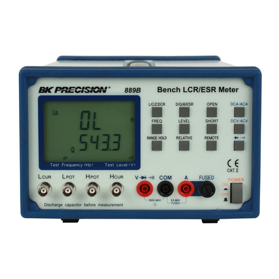
2. Operation 2.1 Physical Description 1. Primary Parameter Display 2. Secondary Parameter Display 3. L/C/Z/DCR Function Key 4. DCA/ACA Function Key 5. Measurement Frequency Key 6. LCUR Terminal 7. Measurement Level Key 8. Range Hold Key 9. Model Number 10. LPOT Terminal 11. -
Page 14: Making Measurement
Open Calibration First, remaining the measurement terminals at the open status, press the Open key then the LCD will display: This calibration takes about 15 seconds. After it is finished, the 889B will beep to show that the calibration is done. -
Page 15: Dc Resistance Measurement
2.2.4 DC Resistance Measurement The DC resistance measurement measures the resistance of an unknown component by 1VDC. Press the L/C/Z/DCR key to select the DCR measurement. The LCD will display: 2.2.5 AC Impedance Measurement The AC impedance measurement measures the Z of an unknown device. Press the L/C/Z/DCR key to select the Z measurement. -
Page 16: Operation Modes
Remote Binning Mode: In the Remote Binning mode, the “RMT Bin” on the LCD will be lit, the operation of 889B is controlled by a remote USB equipped PC or terminal, and the results of the measurement will be simultaneously sent to the local LCD display and remote workstation through the USB port. - Page 17 DC/AC V/A bit position Bit 2 – Bit 0 (test freq) Reserved 100 Hz 120 Hz 1K Hz 10K Hz 100K Hz 200K Hz Reserved Reserved Bit 4 – Bit 3 (test level) Reserved 50 mVrms 250 mVrms 1 Vrms Reserved Bit 5 Reserved...
- Page 18 Open/Short Calibration are turned off and test signal is 1 Vrms in 1 KHz, then the command is as following: MOD 000001111110001011010010 2. The results of the measurement that will be sent from the 889B to a remote PC will be packed in either 7-byte or 11-byte format.
-
Page 19: Remote Mode Command Syntax
Remote Mode: When in the Remote mode, the “RMT” on the LCD will be lit and the 889B is capable of communicating to remote USB equipped PC or terminal through the build-in USB port. The connection setting is as follow:... - Page 20 *IDN? Query the identity of the 889B. This command is used to identify the basic information of 889B. The return value has four fields separated by comma (,). The total length will not greater than 100 characters. The four fields are:...
- Page 21 FREQ? (return) CORR OPEN Perform the open calibration. This command sets the 889B to do the open calibration. After the calibration is done, the 889B will return the “OK” string back. CORR SHORT Perform the short calibration. This command sets the 889B to do the short calibration. After the calibration is done, the 889B will return the “OK”...
- Page 22 Set the measurement level according to the parameter. When setting is done the 889B will return “OK” string. PARAMETER: ASCII string Numerical code 1VDC 1Vrms 250mVrms 50mVrms Example: LEV 1V LEV? Return the current measurement level setting. Example: ASC ON...
- Page 23 Example: ASC ON MODE? DCV V (return value) RANG mV MODE? DCV mV (return value) RANG(?) PARAMETER Set (query) the measurement unit. RANG PARAMETER Set the measurement unit according to the parameter. “OK” string will be returned when setting is complete. PARAMETER: ASCII string Numerical code...
- Page 24 ASC OFF RANG? (return value) READ? Return the measurement value. This command will perform a measurement according to the current measurement mode and return the measured value. Example: READ? 0.22724 0.12840 (return value) READ? 5.1029 (return value) The “DCR”, “DCV”, and “ACV” measurements will send only one measured value. The other measurement modes will send two measured values separated by space (ASCII 20H).
-
Page 25: Application
4. Application 4.1 Test Leads Connection Auto balancing bridge has four terminals (H and L ) to connect to the device under test (DUT). It is important to understand what connection method will affect the measurement accuracy. 2-Terminal (2T) 2-Terminal is the easiest way to connect the DUT, but it contents many errors that are the inductance and resistance as well as the parasitic capacitance of the test leads (Figure 4.1). - Page 26 (a) CONNECTION (b) BLOCK DIAGRAM 1m 10m 100m 1 1K 10K 100K 1M (c) Typical Impedance Measurement Range (Ω) (c) TYPICAL IMPEDANCE MEASUREMENT RANGE (£[) Figure 4.3 5-Terminal (5T) 5-Terminal connection is the combination of 3T and 4T (Figure 4.4). It has four coaxial cables. Due to the advantage of the 3T and 4T, this connection can widely increase the measurement range for 10m...
- Page 27 Figure 4.4 4-Terminal Path (4TP) 4-Terminal Path connection solves the problem that caused by the test lead inductance. 4TP uses four coaxial cables to isolate the current path and the voltage sense cable (Figure 4.5). The return current will flow through the coaxial cable as well as the shield.
-
Page 28: Open/Short Compensation
(Figure 4.7(b)). When the DUT is short, the instrument gets the impedance Zs = Rs + jLs (Figure 4.7(c)). After the open and short compensation, the 889B has Yp and Zs that can then be used for the real Zdut calculation (Figure 4.7(d)). - Page 29 Capacitor The impedance and capacitance in the capacitor are negatively proportional. Therefore, the larger capacitance means the lower impedance, the smaller capacitance means the higher impedance. Figure 4.8 shows the equivalent circuit of capacitor. If the capacitance is small, the Rp is more important than the Rs. If the capacitance is large, the Rs shouldn’t be avoided.
-
Page 30: Limited Three-Year Warranty
6. Safety Precaution SAFETY CONSIDERATIONS The Models 889B LCR Meter has been designed and tested according to Class 1A 1B or 2 according to IEC479-1 and IEC 721-3-3, Safety requirement for Electronic Measuring Apparatus. SAFETY PRECAUTIONS/SAFETY NOTES The following general safety precautions must be observed during all phases of operation, service, and repair of this instrument.
Need help?
Do you have a question about the 889B and is the answer not in the manual?
Questions and answers