
Related Manuals for BK Precision 732A


Summary of Contents for BK Precision 732A
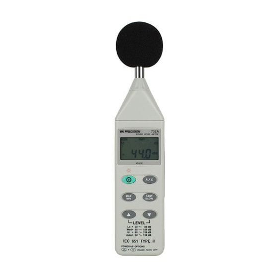
- Page 1 Model: 732A, 735 Digital Sound Level Meter USER MANUAL GlobalTestSupply www. .com Find Quality Products Online at: sales@GlobalTestSupply.com...
-
Page 2: Table Of Contents
CONTENTS Title SAFETY INFORMATION………..……….………….. 1 Environment conditions……………………………..1 Maintenance & Clearing……………………………….1 Safety symbols………………………………………… 1 II. GENERAL DESCRIPTION……………………..…….. 2 III. SPECIFICATIONS..…………………..……………….. 2 IV. NAME AND FUNCTIONS..………….……………….. 5 V. CLOCK & INTV SETUP……….……………….……… 6 DataLogger…………………………………………….. 6 Clock Setup……………………………………………...6 Recording Interval Setup………………………………7 Auto Power Off………………………………………… VI. -
Page 3: Safety Information
I. SAFETY INFORMATION Read t he f ollowing s afety information c arefully b efore at tempting t o oper ate or service the meter. Use the meter only as specified in this manual; otherwise, the protection provided by the meter may be impaired. Environment conditions ... -
Page 4: Specifications
Auto: 30 – 130 dB Accuracy: ±1.5dB (under reference conditions @ 94dB, 1KHz) Dynamic range: 100 dB (50 dB model 732A) Alarm function: “OVER” is when input is more than the upper limit of range. “ UNDER ” is when input is less than the lower limit of range. -
Page 5: Name And Functions
Dimensions (L x W x H): 10.8 × 2.5 × 1.2inch (275 × 64 × 30mm) Weight: 285g (including battery) Accessories: 9V battery, carrying case, Screwdriver, Instruction manual. Windscreen, 3.5 ψ plug, software & RS-232 cable (optional model 732A). IV. NAME AND FUNCTIONS SETUP FAST... - Page 6 ○ Windscreen If you operate at wind speed over 10m/sec, please put protective accessories in front of the microphone. ○ Display SYMBOL FUNCTION 4 digits Max imum indication Mi nimum indication Over range Under range FAST F ast response SLOW Sl ow response A-Weighting C -Weighting...
- Page 7 is available to use (model 735). ○ MAX / MIN hold button Press button to enter the maximum and minimum recording mode. Select the proper Level range before using MAX/MIN to ensure that reading value will not ex ceed t he measurement range. P ress once to s elect MA X v alue. P ress again to select MIN value, and press again to select current value with “...
-
Page 8: Clock & Intv Setup
○ Signal output terminal AC: 1 Vrms Corresponding to each range step. Output impedance ≒ 100Ω Output signal by standard 3.5mm coaxial socket signal. Note: At “Auto” level range, output signal is Auto select on “Lo” or “Med” or “Hi” level range. DC Signal Ground AC Signal... -
Page 9: Recording Interval Setup
Recording Interval Setup: 1: P ress and h old t he “ A/C” but ton and t hen p ower on t he meter: 2: Press “FAST/SLOW"(INTV) button: 3: P ress "REC" ▲ or " LEVEL" ▼ to i ncrease or dec rease number, pr ess “... -
Page 10: Measurement Preparation
Time weighting: FAST Measurement mode: MAX MIN Mode function disable. Level range: 50 to 100dB (2) Insert t he m icrophone h ousing c arefully into t he i nsertion ho le of t he calibrator. (3) Turn on the switch of calibrator and adjust the CAL potentiometer of the unit. The level display will indicate the desired level . -
Page 11: Setup Testlink Ak-73X (Sound Level Meter)- Rs232 Interface Software
response to FAST. To measure average sound level, use the SLOW setting. Select A -weighting f or g eneral n oise s ound l evel and C -weighting f or measuring sound level of acoustic material. (3) Select desired Level. (4) Hold the instrument c omfortably i n ha nd or fix on tripod and point t he microphone at t he s uspected n oise s ource, t he sound pr essure l evel will be displayed. - Page 12 Install TestLink: 1.We recommend closing all other applications before installing the TestLink. 2.Insert setup CD disk to CD disk drive. 3.Choose the Start button on the Taskbar and select Run. 4.Type E:\SETUP and choose OK, then it will copy AK73X.exe (executable file) and help file to your hard disk (default is c:\program files\TestLink\AK73X).
- Page 13 Interface. For better result, the user may close the panel window. Graph Tool Bar - Display or hide Statistic1. - Display or hide Statistic2. - Normal cursor. - When s elected, t he m ouse c ursor will b ecome a c ross s ign when moving t o t he gr aph, c lick on t he graph t o m ark a cross s ign on t he graph.
- Page 14 time and value d isplay on top and r ight s ide of eac h cursor. You c an m ove t he mouse cursor over cursor A or B and click to drag the cursor to move left or right. Right below the cursor A and B is a slider.
- Page 15 When you have the Sound Level DATA LOGGER meter connected to PC and select " DataLogger" from main menu or c lick from t ool bar t o l oad r ecorded data f rom t he m eter and t here will be a pr ogress i ndicator t o s how t he l oading progress.
- Page 16 3.If the connection is successful the panel will display the same value as the Sound Level Meter. I f i t f ailed t o c onnect t he m eter w ith t he PC, i t will display "No Connection" on the panel window in TestLink AK –73X. 4.When the connection is successful, click to start recording real time data and there will be a waveform on the Real Time Graph Window.
- Page 17 (3.) How to load the recorded data from the memory of Sound Level Meter and save it to a file ? (Only for the model with Data Logger) 1. Power on the Sound Level Meter. 2. Press the REC button of the meter to start recording data. 3.
- Page 18 Frequently Asked Question 1. I had connected the Sound Level Meter to PC serial port and turned the meter on, but it still shows "NO CONNECTION". It could be that all serial port are occupied by other application, close Answer: all other application.
- Page 19 Limited One-Year Warranty B&K Precision Corp. warrants to the original purchaser that its products and the component parts thereof, will be free from defects in workmanship and materials for a period of one year from date of purchase. B&K Precision Corp. will, without charge, repair or replace, at its option, defective product or component parts.
- Page 20 Service Information Warranty Service: Please return the product in the original packaging with proof of purchase to the address below. Clearly state in writing the performance problem and return any leads, probes, connectors and accessories that you are using with the device. Non-Warranty Service: Return the product in the original packaging to the address below.
Need help?
Do you have a question about the 732A and is the answer not in the manual?
Questions and answers