
Related Manuals for GORMAN-RUPP PA6D60-4045T


Summary of Contents for GORMAN-RUPP PA6D60-4045T
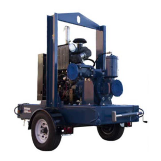
- Page 1 ACDEU OM-06622-02 June 16, 2014 INSTALLATION, OPERATION, AND MAINTENANCE MANUAL WITH PARTS LIST PA SERIES PUMP MODEL PA6D60-4045T GORMAN‐RUPP PUMPS www.grpumps.com 2014 Gorman‐Rupp Pumps Printed in U.S.A.
- Page 2 Register your new Gorman‐Rupp pump online at www.grpumps.com/register. Valid serial number and e‐mail address required. The engine exhaust from this product contains chemicals known to the State of California to cause cancer, birth defects or other reproductive harm. RECORD YOUR PUMP MODEL AND SERIAL NUMBER Please record your pump model and serial number in the spaces provided below.
-
Page 3: Table Of Contents
TABLE OF CONTENTS INTRODUCTION ..........PAGE I - 1 SAFETY ‐... - Page 4 TABLE OF CONTENTS (continued) TROUBLESHOOTING - SECTION D ......PAGE D - 1 PREVENTIVE MAINTENANCE .
-
Page 5: Introduction
PA SERIES OM-06622 INTRODUCTION Thank You for purchasing a Gorman‐Rupp pump. The following are used to alert personnel to proce Read this manual carefully to learn how to safely dures which require special attention, to those install and operate your pump. Failure to do so which could damage equipment, and to those could result in personal injury or damage to the which could be dangerous to personnel:... -
Page 6: Safety - Section A
PA SERIES OM-06622 SAFETY ‐ SECTION A This information applies to Prime Aire damage the pump or endanger person Series pumps. Refer to the manual ac nel as a result of pump failure. companying the engine or power source before attempting to begin oper ation. - Page 7 OM-06622 PA SERIES pipe plugs, or fittings from an over heated pump. Vapor pressure within the pump can cause parts being disen gaged to be ejected with great force. Al Do not operate an internal combustion low the pump to cool completely before engine in an explosive atmosphere.
-
Page 8: Installation - Section B
See Figure 1 for the approximate physical dimen some of the information such as mounting, line sions of this pump. OUTLINE DRAWING Figure 1. Pump Model PA6D60-4045T PREINSTALLATION INSPECTION a. Inspect the pump for cracks, dents, damaged threads, and other obvious damage. -
Page 9: Battery Installation
OM-06622 PA SERIES c. Carefully read all tags, decals, and markings POSITIONING PUMP on the pump assembly, and perform all duties indicated. Note that the pump shaft rotates in the required direction. Death or serious personal injury and damage to the pump or components can occur if proper lifting procedures Only operate this pump in the direction in... -
Page 10: Suction And Discharge Piping
PA SERIES OM-06622 to secure them when filled with liquid and under pressure. Gauges If the pump has been mounted on a mov able base, do not attempt to operate the The pump is drilled and tapped for installing dis pump unless the unit is level. -
Page 11: Sealing
OM-06622 PA SERIES Sealing air to escape from the liquid before it is drawn into the suction inlet. Since even a slight leak will affect priming, head, If two suction lines are installed in a single sump, and capacity, especially when operating with a the flow paths may interact, reducing the efficiency high suction lift, all connections in the suction line of one or both pumps. -
Page 12: Discharge Lines
PA SERIES OM-06622 Figure 2. Recommended Minimum Suction Line Submergence vs. Velocity DISCHARGE LINES Siphoning If the application involves a high discharge head, gradually close the discharge Do not terminate the discharge line at a level lower than that of the liquid being pumped unless a si throttling valve before stopping the pump. -
Page 13: Float Switch Installation
OM-06622 PA SERIES Float Switch Installation pipe is available, attach the float switch cable to the standpipe in the sump at the approxi The Float Switch autostart system employs either a mate desired liquid level. single or double float switch, where a bulb raises or lowers (floats) with the liquid level, thus activating b. -
Page 14: Operation - Section C
OM-06622 PA SERIES OPERATION - SECTION C Review all SAFETY information in Section A. cated (see LUBRICATION in MAINTENANCE AND REPAIR). Follow the instructions on all tags, labels and The pump will begin to prime upon startup. The air decals attached to the pump. in the suction line will be discharged from the educ... -
Page 15: Automatic Starting
OM-06622 PA SERIES AL'. After the engine starts and the unit is fully Liquid Temperature And Overheating primed, adjust the engine RPM until the desired The maximum liquid temperature for this pump is flow rate is achieved. 160_ F (71_C). Do not apply it at a higher operating temperature. -
Page 16: Stopping
OM-06622 PA SERIES vacuum suction gauge readings regularly to detect normal for bearings, and they can operate safely to strainer blockage. at least 180_F (82_C). Checking bearing temperatures by hand is inaccu Never introduce air or steam pressure into the rate. - Page 17 OM-06622 PA SERIES TROUBLESHOOTING - SECTION D Review all SAFETY information in Section A. Before attempting to open or service the pump: 1. Familiarize yourself with this manual. 2. Shut down the engine and discon nect the positive battery cable to en sure that the pump will remain inop...
- Page 18 OM-06622 PA SERIES TROUBLE POSSIBLE CAUSE PROBABLE REMEDY Check strainer and clean if neces Strainer clogged. PUMP STOPS OR FAILS TO DELIVER sary. RATED FLOW OR Check and clean check valve. Discharge check valve clogged. PRESSURE (cont.) Suction intake not submerged at Check installation and correct proper level or sump too small.
- Page 19 OM-06622 PA SERIES TROUBLE POSSIBLE CAUSE PROBABLE REMEDY BEARINGS RUN Bearing temperature is high, but Check bearing temperature regu TOO HOT within limits. larly to monitor any increase. Low or incorrect lubricant. Check for proper type and level of lubricant. Suction and discharge lines not prop...
-
Page 20: Preventive Maintenance Schedule
OM-06622 PA SERIES Preventive Maintenance Schedule Service Interval* Item Daily Weekly Monthly Semi‐ Annually Annually General Condition (Temperature, Unusual Noises or Vibrations, Cracks, Leaks, Loose Hardware, Etc.) Pump Performance (Gauges, Speed, Flow) Bearing Lubrication Seal Lubrication (And Packing Adjustment, If So Equipped) V‐Belts (If So Equipped) Air Release Valve Plunger Rod (If So Equipped) Front Impeller Clearance (Wear Plate) - Page 21 PA SERIES PUMP MAINTENANCE AND REPAIR - SECTION E MAINTENANCE AND REPAIR OF THE WEARING PARTS OF THE PUMP WILL MAINTAIN PEAK OPERATING PERFORMANCE. STANDARD PERFORMANCE FOR PUMP MODEL PA6D60-4045T Based on 70 F (21 C) clear water at sea level Contact the Gorman‐Rupp Company to verify per...
- Page 22 OM-06622 PA SERIES PARTS PAGE ILLUSTRATION Figure 1. Pump Model PA6D60-4045T PAGE E - 2 MAINTENANCE & REPAIR...
- Page 23 OM-06622 PA SERIES Pump Model PA6D60-4045T PARTS LIST (From S/N Up) ITEM PART MAT'L PART NAME NUMBER CODE PUMP END ASSY PA6D60-(SAE 3/10) COMM POWER UNIT KIT 46143-155 BATTERY SEE OPTIONS PUMP MOUNTING KIT 48157-016 NOT SHOWN: PRIME AIRE DECAL...
- Page 24 OM-06622 PA SERIES ILLUSTRATION Figure 2. 46143-155 Power Unit Kit PAGE E - 4 MAINTENANCE & REPAIR...
- Page 25 OM-06622 PA SERIES 46143-155 Power Unit Kit PARTS LIST ITEM PART MAT'L PART NAME NUMBER CODE JOHN DEERE 4045T ENGINE 29224-373 BASE/FUEL TANK 41553-009 24150 LIFTING BAIL KIT 48274-804 MUFFLER GUARD ASSY 42331-061 CONTROL PANEL 48122-543 NEG. BATT CABLE ASSY 47311-133 POS.
- Page 26 OM-06622 PA SERIES ILLUSTRATION Figure 3. PA6D60-(SAE 3/10) COMM Pump Assembly PAGE E - 6 MAINTENANCE & REPAIR...
- Page 27 OM-06622 PA SERIES PARTS LIST PA6D60-(SAE 3/10) COMM Pump Assembly ITEM PART MAT'L PART NAME NUMBER CODE PUMP END ASSY 46133-416 PRIMING CHAMBER KIT 48275-005 CHECK VALVE 6" 26642-126 -FLAPPER 26688-001 -COVER O‐RING 25152-377 HEX HEAD CAP SCREW B1213 15991 LOCK WASHER 15991 HEX NUT...
- Page 28 OM-06622 PA SERIES ILLUSTRATION Figure 4. 46133-416 Pump End Assembly PAGE E - 8 MAINTENANCE & REPAIR...
- Page 29 OM-06622 PA SERIES 46133-416 Pump End Assembly PARTS LIST ITEM PART MAT'L PART NAME NUMBER CODE PUMP CASING SEE NOTE BELOW SUCTION SPOOL 38642-625 10000 WEAR PLATE ASSY 46451-768 PIPE PLUG 10009 . 4A CASING DRAIN PLUG 10009 PIPE PLUG 15079 O‐RING 25154-381...
- Page 30 OM-06622 PA SERIES ILLUSTRATION Figure 5. 44163-549 Repair Rotating Assembly PAGE E - 10 MAINTENANCE & REPAIR...
-
Page 31: Parts List
OM-06622 PA SERIES PARTS LIST 44163-549 Repair Rotating Assembly ITEM PART NAME PART MAT'L ITEM PART NAME PART MAT'L NUMBER CODE NUMBER CODE INTERM GUARD ASSY 42381-509 24152 IMPELLER 38628-036 1102H DRIVE FLANGE GSKT 38683-474 18000 IMPELLER ADJ SHIM SET 48261-057 BRG SNAP RING S720 SEAL ASSY... - Page 32 OM-06622 PA SERIES ILLUSTRATION Figure 6. 48275-005 Priming Chamber Kit ITEM PART MAT'L PART NAME NUMBER CODE PRIMING CHAMBER ASSY 46112-709 PIPE BUSHING AP1608 11999 STREET ELBOW RS08 11999 BALL VALVE 26631-052 STUD C0809 15991 HEX NUT 15991 LOCK WASHER 15991 GASKET 38687-053...
- Page 33 OM-06622 PA SERIES ILLUSTRATION Figure 7. 46112-709 Priming Chamber Assembly PARTS LIST ITEM PART MAT'L PART NAME NUMBER CODE PRIMING VALVE 26664-007 -ORIFICE BUTTON 26688-021 HEX HD CAPSCREW B0806 15991 LOCKWASHER 15991 PRIMING VALVE GASKET 38683-657 19060 PRIMING CHAMBER 38343-020 10000 STRAINER ASSY 46641-222...
- Page 34 OM-06622 PA SERIES ILLUSTRATION Figure 8. 44162-159 Drive Assembly ITEM PART MAT'L PART NAME NUMBER CODE COUPLING ASSY 44165-016 BUSHING 24131-498 -KEY 24113-603 DRIVE FLANGE 38545-004 10000 LOCK WASHER 21171-536 SOCKET HEAD CAP SCREW 22644-220 SOCKET HEAD CAP SCREW BD0606-1/2 15991 CAP SCREW 22645-164...
- Page 35 OM-06622 PA SERIES PUMP AND SEAL DISASSEMBLY lishing that neither personal safety nor pump integrity are compromised by AND REASSEMBLY such practices. Review all SAFETY information in Section A. Follow the instructions on all tags, label and de cals attached to the pump. Before attempting to open or service the This pump requires little service due to its rugged, pump:...
- Page 36 OM-06622 PA SERIES Discharge Check Valve Removal and moved from the pump before lifting. Lift Disassembly the pump or component only as high as necessary and keep personnel away (Figure 3) from suspended objects. Remove the hardware (not shown) securing the discharge check valve bracket to the base.
- Page 37 OM-06622 PA SERIES Separating Pump And Drive Assembly From Loosening Impeller Engine (Figures 5 and 9) (Figure 8) With the pump end separated from the engine, in sert a block of wood through the pump discharge Further disassembly of the pump requires separat and wedge it between the vanes of the impeller ing the pump end from the engine.
- Page 38 OM-06622 PA SERIES nating pattern until the pump casing is pushed off If no further disassembly is required, refer to Seal of the bearing housing. Remove the jacking Installation. screws and shims (26). Shaft and Bearing Removal and Disassembly (Figure 5) Impeller Removal (Figure 5) When the pump is properly operated and main...
- Page 39 OM-06622 PA SERIES To prevent damage during removal from Most cleaning solvents are toxic and the shaft, it is recommended that bearings flammable. Use them only in a well ven be cleaned and inspected in place. It is tilated area free from excessive heat, strongly recommended that the bearings sparks, and flame.
- Page 40 OM-06622 PA SERIES shaft, never press or hit against the outer race, balls, or ball cage. Press only on the inner race. Most cleaning solvents are toxic and Apply a light coating of oil to the lip of the inboard oil seal (26) and press it into the bearing housing with flammable.
- Page 41 OM-06622 PA SERIES RETAINER SEAL PLATE SPRING O‐RING IMPELLER SLEEVE O‐RING IMPELLER SHIMS IMPELLER SHAFT SHAFT SLEEVE ROTATING ELEMENT BELLOWS SPRING CENTERING WASHER STATIONARY SEAT DRIVE BAND Figure 10. Seal Assembly as required before proceeding with seal installa tion. Lubricate the seal sleeve (4) with a small amount of This seal is not designed for operation at light oil and slide the rotating subassembly (con...
- Page 42 OM-06622 PA SERIES face of the impeller. Tighten the nuts evenly to avoid binding. Clearance between the impeller and wear plate is adjusted using the four back cover nuts and lock The shaft and impeller threads must be ing collars. There are 18 detents on the I.D. of each completely clean before reinstalling the im...
- Page 43 OM-06622 PA SERIES and 21). Install the two remaining back cover nuts tating assembly until the wear plate touches the im snugly against the adjusting screws. peller. Measure the gap between the wear plate and the Remove the first two back cover nuts from their impeller at several locations.
- Page 44 OM-06622 PA SERIES If the orifice button was removed, screw the new is secured to the engine bellhousing, with orifice button into the linkage bar until fully seated. out pre‐loading the bearings. Align the hole in the linkage bar with the holes in the bracket and reinstall the pivot pin.
- Page 45 OM-06622 PA SERIES cause the bearings to over‐heat, resulting in pre LUBRICATION mature bearing failure. Seal Assembly NOTE (Figure 4) The white reflector in the sight gauges must be po sitioned horizontally to provide proper drainage. Fill the seal cavity through the hole for the vented plug (7) with SAE No.
- Page 46 For Warranty Information, Please Visit www.grpumps.com/warranty or call: U.S.: 419-755-1280 Canada: 519-631-2870 International: +1-419-755-1352 GORMAN‐RUPP PUMPS...
Need help?
Do you have a question about the PA6D60-4045T and is the answer not in the manual?
Questions and answers