
Related Manuals for G&D DL-DVI-MUX2-NT SERIES


Summary of Contents for G&D DL-DVI-MUX2-NT SERIES
- Page 1 Guntermann & Drunck GmbH www.gdsys.de G&D DL-DVI-MUX2-NT Installation und Bedienung Installation and Operation A9100320-1.00...
- Page 2 Zu dieser Dokumentation Diese Dokumentation wurde mit größter Sorgfalt erstellt und nach dem Stand der Technik auf Korrektheit überprüft. Für die Qualität, Leistungsfähigkeit sowie Marktgängigkeit des G&D-Produkts zu einem bestimmten Zweck, der von dem durch die Produktbeschreibung abgedeck- ten Leistungsumfang abweicht, übernimmt G&D weder ausdrücklich noch still- schweigend die Gewähr oder Verantwortung.
- Page 3 FCC Statement The devices named in this manual comply with Part 15 of the FCC Rules. Opera- tion is subject to the following two conditions: (1) the devices may not cause harm- ful interference, and (2) the devices must accept any interference received, including interference that may cause undesired operation.
-
Page 4: Table Of Contents
Inhaltsverzeichnis Inhaltsverzeichnis Sicherheitshinweise ..................1 Der KVM-Switch ..................... 3 Lieferumfang ....................3 Installation ....................... 4 Übersicht der Schnittstellen ................4 Aufstellen des Geräts ..................4 Anschluss der Geräte des Arbeitsplatzes ............. 5 Anschluss der Rechner ..................6 Verbindung mit bis zu zwei lokalen Netzwerken ..........7 Anschluss der Stromversorgung ................. - Page 5 Inhaltsverzeichnis XML-Steuerung des KVM-Switches ............... 22 Aufbau eines gültigen XML-Dokuments ............22 Auswahl der Geräte ..................22 Verwendung von Geräte-IDs ................23 Verwendung von Port-Angaben ............... 23 Antworten und Meldungen des G&D-Gerätes ..........23 Antworten des Gerätes ................23 Meldungen des Geräts ................23 Mehrere Befehle in einem XML-Dokument kombinieren .........
-
Page 6: Sicherheitshinweise
Sicherheitshinweise Sicherheitshinweise Bitte lesen Sie die folgenden Sicherheitshinweise aufmerksam durch, bevor Sie das G&D-Produkt in Betrieb nehmen. Die Hinweise helfen Schäden am Produkt zu ver- meiden und möglichen Verletzungen vorzubeugen. Halten Sie diese Sicherheitshinweise für alle Personen griffbereit, die dieses Produkt benutzen werden. - Page 7 Sicherheitshinweise Hinweise zum Umgang mit Lithium-Knopfzellen Dieses Produkt enthält eine Lithium-Knopfzelle. Ein Austausch durch den Anwender ist nicht vorgesehen! VORSICHT: Es besteht Explosionsgefahr, wenn die Batterie durch einen falschen Batterie-Typ ersetzt wird. Entsorgen Sie gebrauchte Batterien umweltgerecht. Gebrauchte Batterien dürfen nicht in den Hausmüll geworfen werden.
-
Page 8: Der Kvm-Switch
Der KVM-Switch Der KVM-Switch Der KVM-Switch DL-DVI-MUX2-NT ermöglicht die Bedienung von bis zu zwei Rechnern über einen Arbeitsplatz. HINWEIS: An die MC-Varianten des KVM-Switches können Sie Rechner mit mehreren Videoausgängen anschließen. Die Videosignale dieser Rechner werden auf den separaten Monitoren des Arbeitsplatzes ausgegeben. Der Arbeitsplatz wird mit einer Tastatur und Maus sowie einem Monitor ausgestat- tet. -
Page 9: Installation
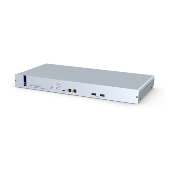
Installation Installation Beim Anschluss der Kabel ist vorzugsweise blockweise und von unten nach oben vorzugehen. So vermeiden Sie, dass bereits gesteckte Kabel die Sicht auf die Bezeichnung der Schnittstellen versperren. Übersicht der Schnittstellen Frontseite des KVM-Switches An der Frontseite des KVM-Switches sind zwei USB 3.0-Schnittstellen zum Anschluss beliebiger USB-Geräte vorhanden. -
Page 10: Anschluss Der Geräte Des Arbeitsplatzes
Installation Anschluss der Geräte des Arbeitsplatzes DVI-I Monitor DVI-I CPU 1 DVI-I CPU 2 Network B RS232 CPU In 1 CPU In 2 Network A PS/2 K/M USB K/M Speaker Line In PS/2 K/M USB K/M USB 3.0 Line In PS/2 K/M USB K/M USB 3.0 Abbildung 2: Schnittstellen zum Anschluss der Geräte des Arbeitsplatzes HINWEIS:... -
Page 11: Anschluss Der Rechner
Installation Anschluss der Rechner HINWEIS: Zum Anschluss der (maximal zwei) Rechner an den KVM-Switch sind die unten aufgeführten Schnittstellen für jeden Rechner verfügbar. Die DVI-Schnittstellen sind am oberen Rand angeordnet. Die übrigen Schnittstel- len sind blockweise am unteren Rand angeordnet. DVI-I Monitor DVI-I CPU 1 DVI-I CPU 2... -
Page 12: Verbindung Mit Bis Zu Zwei Lokalen Netzwerken
Installation Verbindung mit bis zu zwei lokalen Netzwerken Verbinden Sie – falls gewünscht – die Netzwerkschnittstellen mit bis zu zwei lokalen Netzwerken, um aus den Netzwerken auf die Webapplikation Config Panel zuzu- greifen und SNMP-Traps oder Syslog-Meldungen in diese Netzwerke zu senden. DVI-I Monitor DVI-I CPU 1 DVI-I CPU 2... -
Page 13: Inbetriebnahme
Inbetriebnahme Inbetriebnahme Schalten Sie einen Power-Schalter auf der Rückseite des KVM-Switches ein. Sobald das Gerät mit elektrischer Spannung versorgt wird, leuchtet die grüne Power- LED. Der KVM-Switch ist nach dem Startvorgang des Gerätes betriebsbereit. Statusanzeigen Die Geräte-LEDs geben Ihnen die Möglichkeit, den Betriebsstatus jederzeit zu kon- trollieren. - Page 14 Statusanzeigen Bereich Status Bedeutung CPU 1 ... 2 Active Der Kanal ist aufgeschaltet. Der Kanal ist derzeit nicht aufgeschaltet. Status Der angeschlossener Rechner ist eingeschaltet. Es ist kein Rechner angeschlossen oder der Rechner ist ausgeschaltet. 9 · G&D DL-DVI-MUX2-NT...
-
Page 15: Kanal-Umschaltung
Kanal-Umschaltung Kanal-Umschaltung Die Umschaltung auf einen der am KVM-Switch angeschlossenen Rechner errei- chen Sie komfortabel über die Taster am Gerät (s. Seite 10), über die konfigurierten (s. Seite 10) oder über die konfigurierten (s. Seite 11). Select-Keys Step-Keys TIPP: Die erweiterten Möglichkeiten zur Kanalumschaltung (über ein serielles Gerät, über die Webapplikation Config Panel, über das Umschalt-Tool EasyControl, über die XML-Steuerung, oder via SNMP) werden im folgenden Kapitel ab Seite 12 beschrieben. -
Page 16: Umschaltung Mit Step-Keys
Kanal-Umschaltung Umschaltung mit Step-Keys Alternativ zur gezielten Umschaltung auf einen der am KVM-Switch angeschlosse- nen Kanäle mit den Select-Keys (s. vorangegangener Abschnitt) können Sie die Kanäle in auf- oder absteigender Folge mit den Step-Keys umschalten. WICHTIG: Die jeweils aktiven Step-Keys sind von der Auswahl der Select-Keys abhän- gig. -
Page 17: Erweiterte Möglichkeiten Zur Kanalumschaltung
Erweiterte Möglichkeiten zur Kanalumschaltung Erweiterte Möglichkeiten zur Kanalumschaltung Zusätzlich zu den im Kapitel Kanal-Umschaltung auf Seite 10 beschriebenen Optio- nen stehen erweiterte Möglichkeiten zur Kanalumschaltung zur Verfügung. Umschaltung über ein serielles Gerät Die Kanalumschaltung ist über ein serielles Gerät möglich, das an die RS232- Schnittstelle des KVM-Switches angeschlossen ist. -
Page 18: Umschaltung Über Die Webapplikation
Erweiterte Möglichkeiten zur Kanalumschaltung Der KVM-Switch bestätigt die korrekte Ausführung des Befehls durch eine Meldung. Konnte die Umschaltung nicht erfolgen, wird dies durch eine entsprechende Meldung mitgeteilt. Meldung Bedeutung Schaltung auf Kanal erfolgreich ungültige Kanalnummer (out of range) Kanalumschaltung fehlgeschlagen ungültiger Befehl ungültiger Wert (out of range) Umschaltung über die Webapplikation... -
Page 19: Verwendung Des Reset-Tasters
Verwendung des Reset-Tasters Verwendung des Reset-Tasters Auf der Frontseite des Gerätes ist (zwischen der Identification-LED und den Status- LEDs) der Reset-Taster platziert. Mit diesem Taster ist sowohl die Wiederherstellung der Standardeinstellungen als auch die temporäre Deaktierung der Netzfilterregeln möglich. HINWEIS: Um die versehentliche Betätigung des Tasters zu vermeiden, ist dieser hinter einer Bohrung in der Frontblende platziert. -
Page 20: Temporäre Deaktivierung Der Netzfilterregeln
Verwendung des Reset-Tasters Temporäre Deaktivierung der Netzfilterregeln Im Auslieferungszustand des KVM-Switches haben alle Netzwerk-Rechner Zugriff auf die IP-Adresse des Gerätes (offener Systemzugang). Über die Webapplikation können Sie Netzfilterregeln erstellen, um den Zugang zum Gerät gezielt zu kontrollieren. Sobald eine Netzfilterregel erstellt ist, wird der offene Systemzugang deaktiviert und alle eingehenden Datenpakete mit den Netzfil- terregeln verglichen. -
Page 21: Erstkonfiguration Der Netzwerkeinstellungen
Erstkonfiguration der Netzwerkeinstellungen Erstkonfiguration der Netzwerk- einstellungen HINWEIS: Im Auslieferungszustand sind folgende Einstellungen vorausgewählt: IP-Adresse der Netzwerkschnittstelle A: 192.168.0.1 IP-Adresse der Netzwerkschnittstelle B: Bezug der Adresse via DHCP globale Netzwerkeinstellungen: Bezug der Einstellungen via DHCP Grundlegende Voraussetzung für den Zugriff auf die Webapplikation ist die Konfi- guration der Netzwerkeinstellungen des Gerätes, auf welchem die Webapplikation betrieben wird. -
Page 22: Konfiguration Der Netzwerkschnittstellen
Erstkonfiguration der Netzwerkeinstellungen 3. Klicken Sie auf Login 4. Klicken Sie auf das Icon Config Panel 21 Konfiguration der Netzwerkschnittstellen So konfigurieren Sie die Einstellungen einer Netzwerkschnittstelle: WICHTIG: Der Betrieb beider Netzwerkschnittstellen innerhalb eines Subnetzes ist nicht zulässig! HINWEIS: Der Link Local-Adressraum 169.254.0.0/16 ist gemäß RFC 3330 für die interne Kommunikation zwischen Geräten reserviert. -
Page 23: Konfiguration Der Globalen Netzwerkeinstellungen
Erstkonfiguration der Netzwerkeinstellungen Konfiguration der globalen Netzwerkeinstellungen Die globalen Netzwerkeinstellungen stellen auch in komplexen Netzwerken sicher, dass die Webapplikation aus allen Teilnetzwerken erreichbar ist. So konfigurieren Sie die globalen Netzwerkeinstellungen: 1. Wählen Sie den Bereich Globale Einstellungen 2. Erfassen Sie folgende Daten: Betriebsmodus: Wählen Sie den gewünschten Betriebsmodus: ... -
Page 24: Konfiguration Des Kvm-Switches
Konfiguration des KVM-Switches Konfiguration des KVM-Switches Den KVM-Switch können Sie über die Webapplikation Config Panel konfigurieren. Die Webapplikation bietet folgenden Leistungsumfang: übersichtliche Benutzeroberfläche Konfiguration des KVM-Switches Überwachung verschiedener Eigenschaften des Systems erweiterte Netzwerkfunktionen (Netzfilter, Syslog, …) ... -
Page 25: Weiterführende Informationen
Weiterführende Informationen Weiterführende Informationen Pin-Belegung der RS232-Buchse Die Geräte der DL-DVI-MUX-NT-Serie sind mit einer RS232-Buchse ausgestattet. Die Pin-Belegung dieser Buchse zeigt die folgende Abbildung: Die Tabelle zeigt die Zuordnung der verschiedenen Leitungen der Datenverbindung zu den entsprechenden Pins auf: Pin-Nr. Leitung nicht verwendet RxD (Receive Data) -
Page 26: Anschluss Von Usb 3.0-Massenspeichergeräten
Weiterführende Informationen Anschluss von USB 3.0-Massenspeichergeräten An den USB 3.0-Schnittstellen der Frontseite des KVM-Switches können beliebige USB-Geräte angeschlossen werden. Erfolgt die Umschaltung des aktiven Kanals durch den Anwender, steht das USB- Gerät dem bisher aktiven Rechner sofort nicht mehr zur Verfügung. Falls der Rech- ner zu diesem Zeitpunkt Daten auf das Massenspeichergerät schreibt, wird dieser Vorgang abgebrochen. -
Page 27: Xml-Steuerung Des Kvm-Switches
XML-Steuerung des KVM-Switches XML-Steuerung des KVM-Switches Die XML-Steuerung erlaubt die Steuerung des KVM-Switches über Dritthersteller- Geräte (beispielsweise AMX® und Crestron®). Der KVM-Switch verarbeitet die vom Dritthersteller-Gerät über die Ethernet-Schnittstelle empfangenen XML- Befehle. Aufbau eines gültigen XML-Dokuments Die Befehle werden in Form von XML-Dokumenten an das G&D-Gerät übermit- telt. -
Page 28: Verwendung Von Geräte-Ids
XML-Steuerung des KVM-Switches Verwendung von Geräte-IDs Geräte-IDs werden in Antworten und Meldungen der XML-API in hexadezimaler Schreibweise mit dem Prefix ausgegeben. In Befehlen können Sie die Geräte-IDs hexadezimal mit Prefix , oktal mit Prefix oder dezimal angeben. Führende Nullen in der ID sind bei hexadezimaler Schreib- weise optional. -
Page 29: Mehrere Befehle In Einem Xml-Dokument Kombinieren
XML-Steuerung des KVM-Switches Hierfür werden folgende Container benutzt: Fehlermeldungen werden innerhalb des Containers ausgegeben. <Error> Warnungen werden innerhalb des Containers ausgegeben. <Warning> Erfolgsmeldungen und allgemeine Meldungen, die nicht zu den oben aufgeführten Kategorien passen, werden innerhalb des Containers <commandStatus>... -
Page 30: Push-Notifications Abbestellen
XML-Steuerung des KVM-Switches Push-Notifications abbestellen HINWEIS: Die Abbestellung gilt nur für die Verbindung, über welche der unsubs- cribe-Kommando gesendet wurde! Verwenden Sie den -Container, um die Push-Notifications abzubestellen. <unsubscribe> BENACHRICHTIGUNGEN FÜR KANALWECHSEL DEAKTIVIEREN <?xml version="1.0" encoding="utf-8"?> <root> <unsubscribe> <Notification type="channel_select_event"/> </unsubscribe>... -
Page 31: Befehle
XML-Steuerung des KVM-Switches 6. Erfassen bzw. bearbeiten Sie folgende Daten: Zugang: Wählen Sie das Protokoll ( ) oder ( ), über welches die XML-Kommunikation abgewickelt wird. Port: Geben Sie den Port an, über welchen die XML-Kommuni- kation abgewickelt wird. Die Ports 80, 443 und 27996 werden für andere Dienste ver- wendet. -
Page 32: Aufschaltung Des Vorherigen Kanals
XML-Steuerung des KVM-Switches Aufschaltung des vorherigen Kanals Der Befehl <prevmuxchannel> schaltet den vorherigen Kanal des KVM-Switches auf. AUFSCHALTUNG DES VORHERIGEN KANALS <?xml version="1.0" encoding="utf-8"?> <root> <prevmuxchannel/> </root> Monitoring-Werte abfragen Für die Abfrage von Monitoring-Werten wird das XML-Tag verwendet. <monitor> Als Parameter erwartet das Klassen-Tag (beispielsweise ) der <monitor>... - Page 33 XML-Steuerung des KVM-Switches Exemplarisch hier eine Antwort des XML-Dienstes: AUFLISTUNG DER MONITORING-WERTE EINES KVM-SWITCHES <?xml version="1.0" encoding="utf-8"?> <root> <result type="monitor"> <DlMux4> <item> <id>0x11111111</id> <name>MUX-ATC</name> <monitorName>Status</monitorName> <value>1</value> <alarm>off</alarm> <acknowledged>no</acknowledged> </item> </DlMux4> </result> </root> HINWEIS: Neben dem Namen und Wert des jeweiligen Monitoring-Wertes wer- den immer auch die beiden Flags zurückgegeben.
-
Page 34: Technische Daten
Technische Daten Technische Daten Allgemeine Eigenschaften der Serie DL-DVI-MUX2-NT-SERIE Anzahl Videoquellen pro Rechner/Arbeitsplatz: siehe Eigenschaften der Varianten Arbeitsplatz Anschlüsse pro Gerät: Anschluss: direkt am Gerät Schnittstellen Video: siehe Eigenschaften der Varianten für Arbeitsplatz PS/2-Tastatur/-Maus 1 × PS/2-Buchse Adapter für zusätzliche Ausführung der PS/2-Buchse verfügbar USB-Tastatur/-Maus: 2 ×... - Page 35 Technische Daten Video Signaltyp: DVI-I (analoges und digitales Video) Farbmodus digital: 24 Bit DDC: Enhanced Display Data Channel DDC/CI: Das Gerät wurde vorbereitet, um Monitore mit DDC/CI-Funktion zu unterstützen. Die DDC-Informationen werden dabei trans- parent an den Monitor weitergeleitet, um eine größtmögliche Anzahl an Monitoren zu unterstützen.
-
Page 36: Individuelle Eigenschaften Der Varianten
Technische Daten Individuelle Eigenschaften der Varianten DL-DVI-MUX2-NT Anzahl Videoquellen pro Rechner/Arbeitsplatz: 1 Schnittstellen Video: 1 × DVI-I-Buchse für Arbeitsplatz Schnittstellen Video: 1 × DVI-I-Buchse pro Rechner Stromversorgung Stromaufnahme: 0,3 A@240VAC; 0,5 mA@100VAC Gehäuse Material: Aluminium eloxiert Maße (B × H × T): 435 ×... - Page 38 About this manual This manual has been carefully compiled and examined to the state-of-the-art. G&D neither explicitly nor implicitly takes guarantee or responsibility for the qual- ity, efficiency and marketability of the product when used for a certain purpose that differs from the scope of service covered by this manual.
- Page 39 FCC Statement The devices named in this manual comply with Part 15 of the FCC Rules. Opera- tion is subject to the following two conditions: (1) the devices may not cause harm- ful interference, and (2) the devices must accept any interference received, including interference that may cause undesired operation.
- Page 40 Table of contents Contents Safety instructions .................... 1 The KVM switch ....................3 Scope of delivery ....................3 Installation ....................... 4 Overview of the interfaces .................. 4 Setting up the device ..................4 Connecting the workstation devices ..............5 Connecting computers ..................6 Connection to up to two networks ..............
- Page 41 Table of contents Controlling the KVM switch via XML ............22 Structure of a valid XML document ..............22 Selecting devices ..................... 22 Use of device IDs .................... 23 Use of port names ................... 23 Responses and messages of G&D devices ............23 Responses of the device ................
-
Page 42: Safety Instructions
Safety instructions Safety instructions Please read the following safety instructions carefully before you start operating the G&D product. The instructions well help in avoiding damages to the product and in preventing possible injuries. Keep this manual handy for all persons who will be using this product. Follow all warnings or operating instructions which are on the device or stated in this user manual. - Page 43 Safety instructions Instructions on how to handle Lithium button cells This product contains a lithium button cell. It is not intended to be replaced by the user! CAUTION: Risk of explosion if the battery is replaced by an incorrect battery type. Dispose of used batteries in an environmentally friendly manner.
-
Page 44: The Kvm Switch
The KVM switch The KVM switch The KVM switch DL-DVI-MUX2-NT lets you operate up to two computers from one workstation. NOTE: You can connect computers with multiple video outputs to the MC vari- ants of the KVM switch. The video signals of these computers are output on sepa- rate workstation monitors. -
Page 45: Installation
Installation Installation We recommend connecting the cables of the workstation and the computers in blocks and from bottom to top. This prevents cables that are already plugged in from blocking the view of the interface names. Overview of the interfaces Front panel of the KVM switch The front panel of the KVM switch provides two USB 3.0 interfaces to connect any USB devices. -
Page 46: Connecting The Workstation Devices
Installation Connecting the workstation devices DVI-I Monitor DVI-I CPU 1 DVI-I CPU 2 Network B RS232 CPU In 1 CPU In 2 Network A PS/2 K/M USB K/M Speaker Line In PS/2 K/M USB K/M USB 3.0 Line In PS/2 K/M USB K/M USB 3.0 Figure 2: Interfaces for connecting the workstation devices NOTE:... -
Page 47: Connecting Computers
Installation Connecting computers NOTE: To connect (up to two) computers to the KVM switch, the interfaces listed below are available for each computer. The DVI interfaces are placed at the top. The other interfaces are arranged in blocks at the bottom edge. DVI-I Monitor DVI-I CPU 1 DVI-I CPU 2... -
Page 48: Connection To Up To Two Networks
Installation Connection to up to two networks If desired, connect the network interfaces with up to two local networks to access the web application Config Panel from the networks and to send SNMP traps or sys- log messages to these networks. DVI-I Monitor DVI-I CPU 1 DVI-I CPU 2... -
Page 49: Start-Up
Start-up Start-up Turn on a Power switch on the back of the KVM switch. As soon as the device is supplied with voltage, the green Power LED lights up. The KVM switch is ready for operation after the device has booted. Status displays The device LEDs allow you to check the operating status at any time. - Page 50 Status displays Area Status Meaning CPU 1 ... 2 Active Active channel Flashing The devices connected to the »USB 3.0 Devices« inter- face are permanently switched to this channel (pin- ning). Inactive channel Status The connected computer is switched on. No computer is connected or the computer is switched off.
-
Page 51: Switching Between Channels
Switching between channels Switching between channels Switching to one of the computers connected to the KVM switch can be carried out (see page 10), configured (see page 10) or config- buttons on the device select keys ured step keys (see page 11). ADVICE: Advanced ways to switch between channels (via a serial device, the web application Config Panel, the switching tool EasyControl, XML control, or SNMP) -
Page 52: Switching Via Step Keys
Switching between channels Switching via step keys Alternative to using select keys to switch between channels connected to the KVM switch is to use the step keys to switch the channels in ascending or descending order. IMPORTANT: The active step keys depend on the selected select keys. The following table lists the step keys depending on the active select keys. -
Page 53: Advanced Options To Switch Between Channels
Advanced options to switch between channels Advanced options to switch between channels In addition to the options described in the chapter Switching between channels on page 10 you can use advanced options to switch between channels. Switching via serial device Switching between channels is possible via a serial device connected to the RS232 interface of the KVM switch. -
Page 54: Switching Via Web Application
Advanced options to switch between channels The KVM switch confirms the correct execution of the command with a message. A message also informs you if the switching has failed. Message Meaning Successful switching to channel Invalid channel number (out of range) Switching between channels failed Invalid command Invalid value (out of range) -
Page 55: Use Of The Reset Button
Use of the Reset button Use of the Reset button The Reset button is placed on the front of the device (between the Identification LED and the Status LEDs). You can use the button to restore the default settings or to temporarily disable the network filter rules. -
Page 56: Temporarily Disabling The Network Filter Rules
Use of the Reset button Temporarily disabling the network filter rules By default, all network computers have access to the IP address of the system (open system access). You can use the web application to create network filter rules to control access to the device. -
Page 57: Initial Configuration Of The Network Settings
Initial configuration of the network settings Initial configuration of the network settings NOTE: By default, the following settings are preselected: IP address of Network interface A: 192.168.0.1 IP address of Network interface B: Obtain address via DHCP global network settings: Obtain settings via DHCP The basic requirement for accessing the web application is the configuration of the network settings of the device on which the web application is operated. -
Page 58: Configuring The Network Interfaces
Initial configuration of the network settings 3. Click on Login 4. Click on the icon. Config Panel 21 Configuring the network interfaces How to configure the settings of a network interface: IMPORTANT: The operation of both network interfaces within one subnet is not permitted. -
Page 59: Configuring Global Network Settings
Initial configuration of the network settings Configuring global network settings Global network settings ensure that the web application is accessible from all sub- networks, even in complex networks. How to configure global network settings: 1. Select the section Global settings 2. -
Page 60: Configuring The Kvm Switch
Configuring the KVM switch Configuring the KVM switch The web application Config Panel is provided to configure the KVM switch. The web application offers the following features: Clearly arranged user interface Configuration of the KVM switch Monitoring of various system features ... -
Page 61: Further Information
Further information Pin assignment of the RS232 socket The devices of the DL-DVI-MUX2-NT series provide an RS232 socket. The following figures shows the pin assignments of the RS232 socket: The table shows how the different conduits of the data connection are assigned to the according pins: Pin no. -
Page 62: Connecting Usb 3.0 Mass Storage Devices
Further information Connecting USB 3.0 mass storage devices Any USB devices can be connected to the USB 3.0 interfaces on the front panel of the KVM switch. If the active channel is switched by the user, the USB device is no longer provided to the so far active computer. -
Page 63: Controlling The Kvm Switch Via Xml
Controlling the KVM switch via XML Controlling the KVM switch via XML XML enables you to control the KVM switch using third-party devices (e.g. AMX® and Crestron®). The KVM switch uses the Ethernet interface to process any XML commands received from third-party devices. Structure of a valid XML document Any commands are transmitted as XML documents to the G&D device. -
Page 64: Use Of Device Ids
Controlling the KVM switch via XML Use of device IDs For responses and messages of the XML API, device IDs are output as hexadecimal values with the prefix In commands, device IDs can be stated as hexadecimal values with the prefix , as octal values with the prefix or as decimal values. -
Page 65: Combining Multiple Commands In An Xml Document
Controlling the KVM switch via XML The following containers are used for this purpose: Error messages are included in the container <Error> Warnings are included in the container <Warning> Success messages and general messages not fitting the categories given above are out- put within the container <commandStatus>... -
Page 66: Unsubscribing From Push Notifications
Controlling the KVM switch via XML Unsubscribing from push notifications NOTE: The cancellation applies only for the connection on which the unsubscribe command is sent. Use the container to unsubscribe from push notifications. <unsubscribe> DISABLING NOTIFICATIONS FOR SWITCHING BETWEEN CHANNELS <?xml version="1.0"... -
Page 67: Commands
Controlling the KVM switch via XML 6. Enter or edit the following values: Access: Select the protocol ( ) or ( ) to be used to process com- munication via XML. Port: Enter the port to process XML communication. Ports 80, 443 und 27996 are used for other services. They are not available for XML control. -
Page 68: Switching To The Previous Channel
Controlling the KVM switch via XML Switching to the previous channel Use the command <prevmuxchannel> to switch to the previous channel of the KVM switch. SWITCHING TO THE PREVIOUS CHANNEL <?xml version="1.0" encoding="utf-8"?> <root> <prevmuxchannel/> </root> Querying monitoring values Use the XML tag to query the monitoring values. - Page 69 Controlling the KVM switch via XML Here is an example of an answer from the XML service: LISTING THE MONITORING VALUES OF A KVM SWITCH <?xml version="1.0" encoding="utf-8"?> <root> <result type="monitor"> <DlMux4> <item> <id>0x11111111</id> <name>MUX-ATC</name> <monitorName>Status</monitorName> <value>1</value> <alarm>off</alarm> <acknowledged>no</acknowledged> </item> </DlMux4>...
-
Page 70: Technical Data
Technical data Technical data General features of the series DL-DVI-MUX2-NT SERIES Number of Per computer/workstation: See variant features video sources Workstation Connectors per device: Connection: Directly on the device Interfaces Video: See variant features for workstation PS/2 keyboard/mouse 1 ×... - Page 71 Technical data Video Signal Type: DVI-I (analog and digital video) Colour depth: 24 Bit DDC: Enhanced Display Data Channel DDC/CI: The device is ready to support monitors with a DDC/CI function. The DDC informa- tion are transparently forwarded to the monitor to support a maximum number of monitors.
-
Page 72: Individual Variant Features
Technical data Individual variant features DL-DVI-MUX2-NT Number of Per computer/ video sources workstation: Interfaces Video: 1 × DVI-I socket for workstation Interfaces Video: 1 × DVI-I socket per computer Power supply Power consumption: 0,3 A@240VAC; 0,5 mA@100VAC Housing Material: Anodised aluminium Dimensions (W ×... - Page 76 Das Handbuch wird fortlaufend aktualisiert und im Internet veröffentlicht. The manual is constantly updated and available on our website. http://gdsys.de/A9100320 Guntermann & Drunck GmbH Obere Leimbach 9 57074 Siegen Germany http://www.gdsys.de sales@gdsys.de...
Need help?
Do you have a question about the DL-DVI-MUX2-NT SERIES and is the answer not in the manual?
Questions and answers