
Related Manuals for Outdoor Gourmet FSOGBG3002


Summary of Contents for Outdoor Gourmet FSOGBG3002
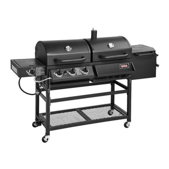
- Page 1 User Manual TRITON ORIGINAL Model #: FSOGBG3002 Please keep this instruction manual for future reference Customer Service: (888) 922-2336, 8:00am to 10:00pm,Monday thru Saturday 9:00am to 8:00pm Sunday Central Standard Time (Made in China)
-
Page 2: Table Of Contents
Table of Contents • Warnings • Tools and Parts • Hardware • Assembly Instructions 8-19 • Care and Maintenance 19-28 • Care and Maintenance 20-29 • Warranty Information Page 2 of 30... -
Page 3: Warnings
Warnings Warnings Warnings Warnings FOR YOUR SAFETY: FOR YOUR SAFETY: FOR YOUR SAFETY: FOR YOUR SAFETY: 1.Read this User Manual before attempting to assemble or operate your grill. 2.Follow all safety instructions. 3.Check for leaks according to directions in this Grill Guide before operating your grill, even if you purchased this grill assembled. - Page 4 Warnings Warnings Warnings Warnings Safety Precautions Always read and follow all DANGER, WARNING, AND FOR YOUR SAFETY notices in this User Manual. Failure to follow these notices may result in property damage, bodily or physical injury, or death. 1. Grill installation must conform with local codes, or in their absence, with either the National Fuel Gas Code, ANSI Z223.1/NFPA 54, Natural Gas and Propane Installation Code, CSA B149.1, or Propane Storage and Handling Code, B149.2.
-
Page 5: Tools And Parts
Tools Required Adjustable wrench (not included) Screwdriver (not included) Page 5 of 30... - Page 6 Parts List 2PCS Page 6 of 30...
-
Page 7: Hardware
Hardware Page 7 of 30... -
Page 8: Assembly Instructions
Assembly Instructions Step 1: Assemble the bottom shelf(23) to the legs(20) using BOLT M6*50 (AA)- 4PCS and NUT M6 FLANGE LOCK (EE)- 4PCS. Step 2: Assemble the long fence rails (21) to both legs using BOLT M6*12 (BB)- 8PCS. Page 8 of 30... - Page 9 Assembly Instructions Step 3: Assemble the threaded casters (22) to legs by twisting clockwise until tight. Turn over the bottom assembly when completed and lock all casters to prevent from moving. Step 4: Assemble the bottom hinges (14)-4PCS to the back of body (15) using BOLT M6*40 (CC)-...
- Page 10 Assembly Instructions Step 5: Align and place body on FIG.1 top of the legs. Using BOLT M6*12 (BB)- 10PCS, attach the triangular bracket left (19) and right (18) to back of body and legs as shown in the Fig.1. Secure front of body to legs using M6*12 (BB)- 2PCS with M6 SPACER (JJ)-2PCS.
- Page 11 Assembly Instructions Step 7: Assemble gas tank holder (24) and gas tank hook (25) on the left leg using BOLT M6*12 (BB)-4PCS. Step 8: Screw in BOLT M6*12 FIG.2b (BB)-2PCS halfway on the upper corners of the side burner body (27) as shown in Fig.
- Page 12 Assembly Instructions Step 9: Mount knob base (26) to front of side burner body using BOLT M4*8 (HH)- 2PCS. Push knob (36) into side burner controller. Step 10: Assemble the side Fig. 3 burner (29) by sliding it on the top center of the side burner body.
- Page 13 Assembly Instructions Step 11: Assemble back panel(1) to back side of gas side using BOLT M6*12(BB)-3PCS. Step 12: Assemble lid Hinges (8)-2PCS on charcoal lid (4) using M6*40 (CC)-4PCS and NUT M6 FLANGE LOCK (EE)-4PCS. Attach the charcoal stack (2)- 1PCS on charcoal lid using BOLT M6*12 (BB)-2PCS and NUT M6 FLANGE LOCK (EE)-...
- Page 14 Assembly Instructions Step 13: Assemble lid hinges (8)-2PCS on gas lid (3) using M6*40 (CC)-4PCS and NUT M6 FLANGE LOCK (EE)-4PCS. Step 14: Assemble the firebox handles (32) and handle bases (31) to firebox lid and body (right) using BOLT M6*25 (DD)-4PCS.
- Page 15 Assembly Instructions Step 15: Fig. 5b Screw in BOLT M6*12 (BB)-2PCS halfway on the firebox (35) as shown in Fig. 5a. Slide in the two screws in opening (Fig. 5b) to hold Fig. 5a the firebox in position. Using M6*12 (BB)- 9PCS, fasten the firebox in place and tighten all screws.
- Page 16 Assembly Instructions Fig. 6 Step 17: Assemble lifting handles (12)-2PCS to charcoal pan (13). Lower lifting system to body (charcoal side) as on Fig. 6. Put flame tamers (11)-3PCS to gas side of body. Step 18: Assemble the warming rack (9)-2PCS by inserting the top two ends to lids and bottom side to body.
- Page 17 Assembly Instructions Step 19: Place cooking grates (33)-2PCS and charcoal pan (34) into firebox. Step 20: Place cooking grates (10)-4PCS to body. Assemble “S” hooks (5)-4PCS to accessory holder. Page 17 of 30...
- Page 18 Assembly Instructions Step 21: Slide drip trays (16)- 2pcs underneath each side of the body. Install battery to ignition button by gently removing the cap, placing battery (II) and putting back the cap. Page 18 of 30...
- Page 19 FULLY ASSEMBLY Page 19 of 30...
-
Page 20: Care And Maintenance
GAS GRILL General Information and Instructions Your new Outdoor Gourmet™ Grill has been designed and manufactured to high quality standards. It will provide you with many years of enjoyment with a minimal amount of maintenance. Please keep in mind the following FOR YOUR SAFETY. - Page 21 WARNING 1. Do not attempt to use a cylinder with any other type of connection device. 2. Do not attempt to use a cylinder with a larger capacity WARNING A frosty cylinder valve indicates possible gas overfill. Close the LP valve and call your dealer immediately.
- Page 22 Regulator and LP Cylinder Connections CAUTION The gas pressure regulator provided with this outdoor cooking appliance must be used. This regulator is set for an outlet pressure of 11 inches water column. Your regulator is equipped with a Q.C.C. Type 1 quick connect system. It will not allow gas to flow until a positive seal has been made.
- Page 23 LEAK TESTING THE REGULATOR, VALVES, HOSES, AND CONNECTIONS 1. Ensure the LP cylinder valve and all burners are “Off”. 2. Ensure the LP cylinder is connected to the regulator. 3. If the information in the above steps is not followed exactly, a fire causing death or If the information above is not followed exactly, a fire causing death or serious injury may occur.
- Page 24 Grill Operations LIGHTING Always visually inspect your grill before lighting. Replace any hoses that are frayed or cracked before lighting your grill. Look for anything that may be blocking spaces for ventilation and remove. After lighting, always check the flame to ensure you have a good flame all along each burner. If not able to light, or the flame is not even along the entire burner(s), then see the Trouble Shooting section WARNING 1.
- Page 25 TURNING OFF YOUR GRILL 1. Turn off the gas supply at the LP tank by turning the valve clockwise. 2. Turn all burner control knobs to the “Off” position. Cleaning Your Grill WARNING 1. Do not clean any part of your barbecue grill in a self-cleaning oven. 2.
- Page 26 CLEANING THE BURNERS 1. Ensure the LP gas is turned off at the LP cylinder. 2. Remove the cooking grates, flame tamer, and grease tray. 3. Remove the cotter pins located underneath the back end of each burner. 4. Lift each burner up and out. 5.
- Page 27 Grilling With Your New Grill Welcome to the world of grilling. Whether you’re already an established griller, or just starting out, your new grill should bring you much enjoyment and satisfaction, to say nothing of some phenomenal meals. We encourage you to experiment to find your own favorite recipes. The control panel is labeled “HI/LIGHT”, “LOW”, and “OFF”...
- Page 28 10. Turn foods infrequently. Generally, only turn a steak once during cooking. 11. Use tongs rather than a fork when turning the food on the grill. Less juice will be lost that way. 12. Know your sauce and when to apply. Oil and vinegar based sauces can be brushed on any time. Sugar based sauces like barbecue sauce should be applied during the last few minutes of cooking.
- Page 29 Frequently Asked Questions Can I convert my gas grill from one fuel source to another? No. Your gas grill is manufactured to specific standards developed by CSA and ANSI for your safety and grilling performance for either LP or Natural Gas. We do not offer conversion kits nor do we recommend you change the fuel type.
-
Page 30: Warranty Information
Warranty Information 1-888-922-2336 8:00 am to 10:00pm Monday thru Saturday 9:00am to 8:00pm Sunday, Central Standard Time Page 30 of 30...
Need help?
Do you have a question about the FSOGBG3002 and is the answer not in the manual?
Questions and answers