Table of Contents
Advertisement
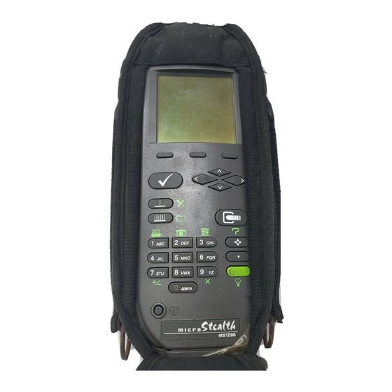
OPERATION MANUAL
MODEL MS1200
SCANNING SIGNAL
LEVEL METER
This document contains information proprietary to
Wavetek. The information in this document
is not to be used or duplicated in any manner without
the prior approval, in writing, of Wavetek.
Wavetek
Wavetek
Wavetek
Wavetek
Wavetek
Communications Division
5808 Churchman Bypass
Indianapolis, IN 46203-6109
(800)851-1198
(317)788-5960
Fax: (317)782-4607
8/95
Manual Part No.
6510-00-0281
1
Advertisement
Table of Contents

Subscribe to Our Youtube Channel
Summary of Contents for Wavetek MS1200
- Page 1 MODEL MS1200 SCANNING SIGNAL LEVEL METER This document contains information proprietary to Wavetek. The information in this document is not to be used or duplicated in any manner without the prior approval, in writing, of Wavetek. Wavetek Wavetek Wavetek Wavetek Wavetek...
- Page 2 This warranty is not transferrable and does not apply to used or demonstration products. The obligation of Wavetek arising from a Warranty claim shall be limited to repairing, or at its option, replacing without charge, any assembly or component (except batteries) which in Wavetek’s sole opinion proves to be defective within the scope of the Warranty.
-
Page 3: Table Of Contents
Contents Introducing microStealth ..............5 Introduction ..................5 Getting Acquainted with the Keypad ..........7 Getting Acquinted with the Screen ........... 9 The Navigator ..................12 Configuring microStealth ..............12 Global Configuration ................13 Measurements Configuration ............. 16 Channel Plan Configuration ............... 19 Using microStealth ................ - Page 4 Moving the Marker................40 Selecting the Low and High Carriers ..........40 Adjusting the Reference Level ............40 Adjusting the Scale ................40 Measurement Hold ................40 Printing the Screen ................41 Scan .......................41 Moving the Marker................41 Adjusting the Reference Level ............41 Adjusting the Scale ................42 Checking Limits ..................
-
Page 5: Introducing Microstealth
MODEL MS1200 Introducing microSTEALTH INTRODUCTION The MS1200 Signal Level Meter is a high performance instrument designed for cable television technicians. The durable, waterproof MS1200 makes innovative use of a graphics LCD to simplify operation. The LCD backlight makes measurements easier in crawl spaces and behind TVs. -
Page 7: Getting Acquainted With The Keypad
You can also print a report that lists all configuration settings including the channel plan. The MS1200 tunes from 45 to 550 MHz with an option to extend the range to 5 to 890 MHz. - Page 8 FULL SCAN MODE View a spectrum graph of all carrier levels in your channel plan. NAVIGATOR Instantly "travel" to any mode using the NAVIGATOR. ENTER KEY Press this key to terminate your entry or selection. 5. ALPHANUMERIC KEYS You use the alphanumeric keys to enter data while operating your microStealth.
-
Page 9: Getting Acquinted With The Screen
Print a measurement screen, installation report, or configuration report to a serial printer. Note: The following secondary function is not available on the MS1200: FILE GETTING ACQUAINTED WITH THE SCREEN There are certain elements of the screen that will become familiar to you as you use your microStealth. - Page 10 Title Bar Indicators You may see indicators appear above the title bar from time to time. This is what they represent: This indicator appears in the top right-hand corner of the screen when you press the SHIFT key. This means that microStealth interprets the next key that you press to be a secondary function.
- Page 11 A list can be either "active" or "inactive". You can tell by looking at the border. If the border is solid, the list is active and any keys that you press are directed toward it. If the border is dim, the list is inactive and is not affected by key presses.
-
Page 12: The Navigator
THE NAVIGATOR You can easily travel to any mode using the NAVIGATOR. To access the NAVIGATOR, press the key. An icon appears on the screen for each available mode. Use the up, down, left, and right arrows to highlight the icon that represents the mode you want to use. -
Page 13: Global Configuration
To configure your microStealth, press the SHIFT + keys or choose the icon from the NAVIGATOR. The following screen appears: Configuration settings are divided into three categories; GLOBAL, MEASUREMENTS, and CHANNEL PLAN. Use the up and down arrows to highlight the category you want and then press the key. - Page 14 CONTRAST LEVEL Adjusts the contrast level of the LCD for optimum viewing. SHUTOFF TIME-OUT Sets the amount of inactive time allowed before your microStealth turns off automatically. This feature is useful for conserving battery life by preventing the microStealth from being left on accidentally when it is not in use.
- Page 15 Baud Rate: same as your microStealth Date Bits: Stop Bits: Parity: NONE Flow Control: Xon/Xoff Important The baud rate of both your microStealth and your printer must match (see BAUD RATE). A serial to parallel converter (such as the on manufactured by Black Box Corp.) can be used for printing to a parallel printer.
-
Page 16: Measurements Configuration
Factory Default Sets all stored preferences to factory presets. Press the key to initiate the default operation. Important All stored settings are lost when you perform this operation. Test Display Exercises all pixels on the LCD for test purposes. Re- peated pressing of the key sequences the display between all pixels "on", all pixels "off", and the display test... - Page 17 SCAN AUDIO CARRIERS Select YES if you want to see the audio carriers in the full scan screen. You can achieve a faster scan by omitting the audio carriers. SCAN SCRAMBLED CHANNELS Scrambled channels require more time to measure. You can achieve a faster scan by omitting scrambled channels.
- Page 18 You can change the name of the USER DEFINED (CUSTOM) test point. Notice that the edit box appears when this test point is highlighted. When you press the key, the edit box becomes active and you can enter any name up to fifteen characters long. Be sure to press the key when finished to terminate your entry.
-
Page 19: Channel Plan Configuration
You can edit the value of the highlighted limit by pressing the key. When the edit box becomes active, enter the desired value. Be sure to press the key when finished to terminate your entry. Press the soft key to return all limits in the test point to their factory preset values. - Page 20 Step 1 You are asked to enter a name for the channel plan. Using the edit box, you can enter any name up to fifteen charac- ters long. Be sure to terminate your entry with the key. Press the soft key to continue with the next step. Step 2 There are several standard channel plans to use as a foundation for building your plan.
- Page 21 You must enable a channel in order to perform measurements on it. A check mark appears in the left-hand column when the channel is enabled. When you built the plan, microStealth automatically enabled all the channels it found to be active on your system. You may want to verify that all your channels have been correctly enabled.
- Page 22 Use the up or down arrow to highlight the desired parameter. Press key to edit the selected parameter. After completing your entry, be sure to press the key again. Enabled As mentioned earlier, a channel must be enabled in order for it to be measured.
- Page 23 Important microStealth supports several scrambling formats including the following: Horizontal Sync Suppression Audio Offset (TV and DUAL type only) This is the offset between the video and audio carriers in MHz. Audio Offset 2 (DUAL type only) This is the offset between the video and second audio carriers in MHz.
- Page 24 Up to six channels can be selected. To select a channel, use the up or down arrow to highlight the desired channel in the list, then press softkey. A check mark appears in the left-hand column of the list indicating that this is now a TILT channel. Also, the channel number appears in one of the six boxes above the list.
- Page 25 These are the packages that will be available to you when you edit a channel. You will be able to select from one of these packages for each channel in the plan. To enable a package, press the softkey. A check mark appears in the left-hand column to indicate that the package is enabled.
- Page 26 COPY REMOTE PLAN You can easily copy a channel plan from one microStealth unit to another. This saves you time when configuring multiple units. First, connect a cable between the two microStealth units. Select COPY REMOTE PLAN only on the unit that you want to copy the channel plan to.
-
Page 27: Using Microstealth
INTRODUCTION The best way to learn about microStealth is to use it. Section 2 discusses the individual measurements available with the MS1200. Each measurement mode discussion includes detailed descriptions on how to perform the measurement as well as operating controls and indicators. -
Page 28: Selecting Channel Packages
SELECTING CHANNEL PACKAGES If you have configured channel packages, a list of available pack- ages will appear. From this list, you can select the packages that the subscriber has ordered. The number to the right of the package name tells you how many channels are included in each package. Use the up or down arrows to highlight a package and then press the soft key to select it. -
Page 29: Installation Results Summary
Note Be sure that you have enabled all of the test points that you are interested in using. The soft key is only available if there is more than one enabled test point. (see EDIT TEST POINTS). Important Only the limits that are enabled in the selected test point are checked (see EDIT TEST POINTS). -
Page 30: The Channel List
THE CHANNEL LIST Press the soft key or to sequence to the channel list screen. In addition to using the keys, you can also use the left and right arrows to sequence through the results screens. The channel list provides essential information about each channel. In the list you will find the channel number in the first column followed by the label. -
Page 31: Channel Measurement
Adjacent Channel Failures lower adjacent channel level upper adjacent channel level both upper and lower adjacent channel levels Video Level Failures video level too high video level too low DVA Failures DVA too high DVA too low CHANNEL MEASUREMENT Press the soft key or to sequence to the channel measure- ment screen. -
Page 32: Printing An Installation Report
PRINTING AN INSTALLATION REPORT Press the SHIFT + keys to print a comprehensive report of the installation results. A bar graph appears indicating the status of the printout. The report lists level measurements for all the channels that you installed and indicates out-of-limit conditions with an overall PASS/FAIL conclusion. -
Page 33: Adjuisting The Reference Level
ADJUSTING THE REFERENCE LEVEL You can adjust the reference level setting of the analog bar meter using the up and down arrows. When you press the SHIFT + keys, your microStealth automatically sets the optimum reference level for you. TUNING BY CHANNEL When you are tuned to a channel, both the video and audio carriers of the channel are measured and displayed simultaneously. -
Page 34: Measurement Hold
MEASUREMENT HOLD You can freeze the level measurement at any time by pressing the SHIFT + keys. The measurement is retained even if the cable is disconnected from the input port. Notice that the mode icon in the upper left-hand portion of the screen appears inverted while the measurement is on hold. -
Page 35: Full Scan
Error A hardware problem exists. If this condition persists, the unit may need repair. FULL SCAN Press the key to select the FULL SCAN mode or choose the icon from the NAVIGATOR. A spectral graph of all the carriers in the channel plan appears. MOVING THE MARKER A vertical marker appears over the currently selected channel. -
Page 36: Adjusting The Reference Level
ADJUSTING THE REFERENCE LEVEL The reference level setting is displayed above the graph. This is the level at the very top line. You can adjust the reference level using the up and down arrows. When you press the SHIFT + keys, your microStealth automatically sets the optimum reference level for you. - Page 37 Press the soft key to sequence through the available test points. The test point that you have selected is represented in the upper portion of the screen by one of the following icons: Subscriber Drop Ground Block User Defined Note Be sure that you have enabled all of the test points that you are interested in using.
-
Page 38: Checking Limits On An Individual Channel
Note Only the limits that are enabled in the selected test point appear on this screen. Your microStealth can indicate the minimum and maximum carrier level limits on the graph. The out-of-limit portions appears as diagonal “hash” areas. You can toggle the hash lines on and off by pressing the key. -
Page 39: Measurement Hold
MEASUREMENT HOLD You can freeze the scan measurement at any time by pressing the SHIFT + keys. The measurement is retained even if the cable is disconnected from the input port. Notice that the mode icon in the upper left-hand portion of the screen appears inverted while the measurement is on hold. -
Page 40: Moving The Marker
MOVING THE MARKER You can view up to six carriers. A vertical marker appears over the currently selected carrier. The channel number, type and label appear in the upper right-hand portion of the screen. The fre- quency and level of the selected carrier can be seen directly beneath the graph. -
Page 41: Printing The Screen
You can print the entire screen at any time by pressing the SHIFT keys. A bar graph appears indicating the status of the printout. SCAN The MS1200 includes an additional SCAN mode that can display up to six video carriers. You can access this mode by choosing the icon from the NAVIGATOR. -
Page 42: Adjusting The Scale
ADJUSTING THE SCALE The scale setting is displayed above the graph. You can adjust the scale to provide the best view of the carrier levels by pressing the soft key. A new set of soft keys appears. Use the soft keys to increment and decrement the scale value. Press the soft key when you have finished. -
Page 43: Measurement Hold
You can quickly check to see if all SCAN carriers are within limits by looking at the PASS/FAIL indicator above the graph. MEASUREMENT HOLD You can freeze the scan measurement at any time by pressing the SHIFT + keys. The measurement is retained even if the cable is disconnected from the input port. -
Page 45: Reference
MODEL MS1200 Reference USING THE REFERENCE SECTION This section provides additional information concerning the use of the MS1200. Items to be discussed include; Help, Information, and Technical Support. HELP The HELP mode provides on-line user assistance by means of context-sensitive help screens. During normal operations, soft key icons appear at the bottom of the display. -
Page 46: Information
If an icon is currently inactive "feature not available" is displayed. INFORMATION Choose the icon from the NAVIGATOR. Here you can view information concerning your MS1200. The type of information includes; model, frequency range, serial #, firmware version, calibra- tion date, and channel plan. -
Page 47: Technical Support
TECHNICAL SUPPORT Although we've worked hard to make the MS1200 as easy-to-use as possible, the wide range of cable television applications can make proper operation a difficult task. If you have a problem using your unit you can contact Wavetek's Technical Support for help. You can reach Wavetek's Technical Support, Monday through Friday between 8 am and 5 pm at (317) 788-5960. -
Page 49: Appendix A: Specifications
MODEL MS1200 Appendix A: Specifications SPECIFICATIONS Frequency Range: 45 to 550 MHz; 45 to 890 MHz (optional); sub band option (5 to 45 MHz) Accuracy: +10kHz @ 25°C; (+20 kHz over temp.) Resolution Bandwidth: 300 kHz Tuning Resolution: 25 kHz... - Page 50 Powering Battery Life: 3 hours continuous (backlight off), re placeable battery cartridge Charge Time: 16 hours with unit off; 30 hours slow charge (with unit operating) Standard Accessories 4010-00-0114: microStealth AC/DC charger/adapter 1219-00-1223: Battery cartridge for microStealth Options MSUHF; Frequency extension to cover range: 45 to 890 MHz Sub Option: Frequency extension to include 5 to 45 MHz microStealth Carrying Case;...
-
Page 51: Appendix B: Power Management And Battery
Management and Battery Battery Pack Location and Installation The MS1200 battery pack is located on the back of the unit. To remove or replace the battery pack, pull the notched tab downward, and lift up the battery pack. To install the battery pack, insert the bottom of the pack into the groove and press down on the battery pack until it clicks into place. -
Page 53: Appendix C: Interface Port
Appendix C: Interface Port CONNECTOR The MS1200 has a serial interface with RS232 drive, using a 3-pin stereo connector. The serial interface has a driver built in for RS232 serial binary data interchange. The connector is located on the bottom of the unit behind a waterproof cover. -
Page 54: Cable Specifications
CABLE SPECIFICATIONS MICROSTEALTH TO PC MICROSTEALTH TO PRINTER(STANDARD) - Page 55 MICROSTEALTH TO MICROSTEALTH MICROSTEALTH TO PRINTER(CITIZEN)
Need help?
Do you have a question about the MS1200 and is the answer not in the manual?
Questions and answers