Table of Contents
Advertisement
Quick Links
Advertisement
Table of Contents

Related Manuals for Crestron STX-1700C


Summary of Contents for Crestron STX-1700C
- Page 1 Crestron STX-1700C 2-Way RF Wireless Touchpanel Operations Guide...
- Page 2 This document was prepared and written by the Technical Documentation department at: Crestron Electronics, Inc. 15 Volvo Drive Rockleigh, NJ 07647 1-888-CRESTRON All brand names, product names and trademarks are the property of their respective owners. ©2004 Crestron Electronics, Inc.
-
Page 3: Table Of Contents
Crestron STX-1700C Contents 2-Way RF Wireless Touchpanel: STX-1700C Introduction ... 1 Functions and Features ... 1 Roaming Feature ... 2 Specifications ... 3 Physical Description... 4 Industry Compliance ... 6 Setup ... 6 Applying Power... 6 Identity Codes... 7 Configuring the Touchpanel... 8 General Use and Safety ... -
Page 5: 2-Way Rf Wireless Touchpanel: Stx-1700C
STXI-1700C. Functional Summary NOTE: The STX-1700C is supplied with an optional bezel, two 5-button switch actuators, and ten black pushbuttons (blank), five for each side of the LCD screen. You can use these buttons to access any frequently used commands. Refer to Operations Guide - DOC. -
Page 6: Roaming Feature
Roaming Feature This feature allows an STX-1700C to extend its range from room to room by using multiple STRFGWX RF gateways. For proper communication, the RF Channel (refer to “Cresnet Interface Menu” on page 9) must be the same for the touchpanel with respect to all gateways in the system. -
Page 7: Specifications
Battery life is 180 minutes continuous usage with background lighting at full brightness. Actual operating time depends on usage and settings for background brightness and timeouts. The latest versions can be obtained from the Crestron website. Refer to NOTE after last footnote. 2-Way RF Wireless Touchpanel: STX-1700C • 3... -
Page 8: Physical Description
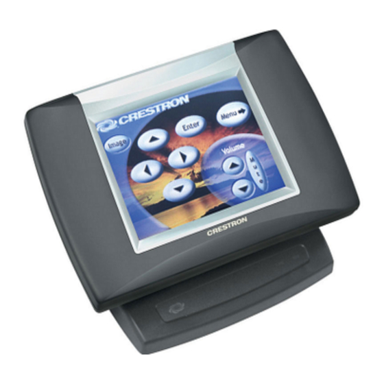
(including the FTP site). Physical Description The touch-sensitive viewing screen is located on the front of the STX-1700C. The electronic hardware is housed in a black and silver molded plastic enclosure, shown below. - Page 9 2-Way RF Wireless Touchpanel 5.01 in (12.73 cm) 8.75 in (22.22 cm) 5.51 in (14.00 cm) 3.85 in Cresnet upload connector 2-Way RF Wireless Touchpanel: STX-1700C • 5 3.56 in (9.04 cm) 5.70 in (14.48 cm) 4.24 in (10.76 cm) Power connector...
-
Page 10: Industry Compliance
Setup Applying Power The touchpanel can be powered via the ST-BTPN, while docked in the ST-DSN, or via the external power pack. Each of these items has its own Operations Guides which details proper usage. Refer to the table below for the required document number. -
Page 11: Identity Codes
Crestron STX-1700C Identity Codes The STX-1700C touchpanel uses three distinct types of identity (ID) codes for recognition within a Cresnet system: Cresnet identity (Net ID), RF ID, and RF CHANNEL. These codes are assigned to the touchpanel from the Cresnet Interface Menu when the unit is configured. -
Page 12: Configuring The Touchpanel
To configure the unit, it may be necessary to access a series of setup screens prior to viewing run-time screens that are loaded into the touchpanel for normal operation. The MAIN MENU for configuring the touchpanel appears when a finger is held for about five seconds from the power off state. - Page 13 The touchpanel can be set to one of fifteen numbers; “1” is shown as an example in the illustration and is the default. The RF ID setting should match the value assigned to the STX-1700C touchpanel definition in the SIMPL Windows program. Refer to “C2Net-Device Slot in Configuration Manager”...
- Page 14 ENABLED and DISABLED. With ENABLED selected, the display comes on when one of the “quick” pushbuttons is pressed. With DISABLED selected, the display stays off when a “quick” pushbutton is pressed (if touchpanel was off, it goes to standby). The default is DISABLED.
-
Page 15: Diagnostics Menu
NOTE: If the external AC power pack is attached to the touchpanel and plugged into an active AC receptacle or if the touchpanel is resting in the docking station (ST-DSN) and plugged into an active AC receptacle, the panel does not power down when the power down timeout is achieved. -
Page 16: General Use And Safety
Crestron’s True Blue Support, log in at http://support.crestron.com. First-time users will need to establish a user account. You can create a program that allows you to set up the STX-1700C to operate a Crestron control system using the Crestron programming tools Crestron SystemBuilder™... -
Page 17: Programming With The Crestron Systembuilder
If not, refer to the extensive help information provided with the software. NOTE: In the following description, the PRO2 control system is used. NOTE: The STX-1700C can operate as a wired panel when set correctly in the SIMPL program. This is recommended to troubleshoot the program code and to eliminate wireless/RF configuration issues before running the program in wireless mode. -
Page 18: C2Net-Device Slot In Configuration Manager
Expanded PRO2 System Tree C2Net-Device Slot in Configuration Manager To incorporate an STX-1700C into the system, a gateway device is required. The C2Net-Device Slot can accept a gateway such as the STRFGWX. Once a gateway is configured in a C2Net-Device Slot, the slot allows Cresnet communication between the touchpanel and the control system. - Page 19 Crestron STX-1700C “Device Settings” Window for the STRFGWX Similarly, expand the system tree in the lower pane and double-click the STX-1700C icon to open the “Device Settings” window for the touchpanel. Select the RF/IR ID tab to change the touchpanel RF ID, as shown below. For more information on setting the RF/IR ID, refer to “RF Setup”...
- Page 20 STX-1700C Input/Output Signals The STX-1700C symbol provides up to 999 digital joins, up to 256 analog joins, and up to 127 serial input joins. The programmer selects the signal types by clicking on the appropriate button at the top of the Symbol Detail view when programming the panel.
- Page 21 For example, the logic in the original STX-1700C symbol at RF ID 01 must be copied and pasted Operations Guide - DOC. 6226A...
-
Page 22: Programming With Vt Pro-E
STX-1700C symbol at RF ID 01. The logic in the original STX-1700C symbol at RF ID 02 must be copied and pasted in the new STX-1700C symbol at RF ID 02. To do this for RF ID 01 (in Program View), place the arrow cursor on the original touchpanel at RF ID 01. -
Page 23: Uploading And Upgrading
Assigning 17509 (Out of Range) to a page, sub page or button activates the page, subpage or button when the STX-1700C goes out of range (is no longer communicating with an STRFGWX). "I" indicates that pressing a button with this join number commands the touchpanel to perform the function. -
Page 24: Communication Settings
Crestron e-Control Reference Guide (Doc. 6052) or the respective Operations Guide for the control system. These documents are available from the Crestron website. Refer to the figure on the next page for a typical connection diagram when uploading files. - Page 25 RJ-11 cable. NOTE: The RJ-11 (part of ST-PK) and ST-CBL cables can also be found as part numbers CNSP-585 and CNSP-586, respectively, in the Crestron cable database. The database can be downloaded from the Crestron website. NOTE: The procedure on the next page uses the ST-CBL.
- Page 26 2-Way RF Wireless Touchpanel Programming Cable Specifications 22 • 2-Way RF Wireless Touchpanel: STX-1700C 1. Before making any connections to the touchpanel, verify that the control system is properly connected to the PC (using an RS-232 DB9 straight-through cable, Crestron P/N CNSP-587) and powered on.
- Page 27 RTS/CTS is selected. Click the OK button to save the settings and close the window. 8. Proceed to “Uploading a VT Pro-e Project” on the next page, or to “Firmware Upgrade” that begins on page 25 as appropriate. 2-Way RF Wireless Touchpanel: STX-1700C • 23...
-
Page 28: Uploading A Vt Pro-E Project
2. As shown below, select File Transfer | Send Touchpanel (alternatively, depress Alt+T) from the Viewport menu. 3. As shown below, select the Net ID of the STX-1700C and then click OK. The “Touchpanel Transfer” window appears (refer to the following graphic). -
Page 29: Firmware Upgrades
2. As shown on next page, select File Transfer | Update Touchpanel Firmware from the Viewport menu. 3. As shown on the next page, select the Net ID of the STX-1700C and then click OK. 2-Way RF Wireless Touchpanel: STX-1700C • 25... - Page 30 2-Way RF Wireless Touchpanel “Select Network ID” Window Select CSF File 26 • 2-Way RF Wireless Touchpanel: STX-1700C 4. As shown below, select the firmware (CSF) file and click Open. The transfer will complete automatically. 5. Disconnect the programming cable and the external power pack from the touchpanel.
-
Page 31: Problem Solving
Problem Solving Troubleshooting The table below and continued on the next page provides corrective action for possible trouble situations. If further assistance is required, please contact a Crestron customer service representative. NOTE: To minimize system diagnostics and troubleshooting, Crestron recommends defining the touchpanel as a wired unit in SIMPL Windows, then test functionality as a wired network device prior to testing the STRFGWX transceiver operations. -
Page 32: Out Of Range Feature
Crestron recommends that you use the out of range feature. Out of Range Feature Active When the STX-1700C is out of range, it displays an out of range indication of your choice (refer to “Optional Pushbuttons” on page 18), and the touchpanel does not respond. -
Page 33: Further Inquiries
For assistance in your local time zone, refer to the Crestron website (http://www.crestron.com/) for a listing of Crestron worldwide offices. You can also log onto the online help section of the Crestron website to ask questions about Crestron products. First-time users will need to establish a user account to fully benefit from all available features. -
Page 34: Appendix A: Optimum Rf Reception Guidelines
(no obstructions between gateway and receiver). Crestron recommends that the gateway is at least five to six feet high for best results. Avoid placing transceivers or transmitters at a low height or on the ground. - Page 35 Operations Guide - DOC. 6226A 2-Way RF Wireless Touchpanel Building Top of gateway Building RF GATEWAY - 2 WAY P WR CRESTRON Front of gateway Building Top of gateway Antenna 2-Way RF Wireless Touchpanel: STX-1700C • 31 Antenna Antenna ANTENNA STRFGWX...
-
Page 36: Appendix B: Installation Of Optional Pushbuttons
Crestron Engraver software. Version 2.3.0.0 or later is available from the Crestron website. Perform the following to install pushbuttons on the STX-1700C. Follow these same basic procedures to replace the blank buttons with the optional engraved buttons. A #1 Phillips screwdriver is required. -
Page 37: Software License Agreement
This Agreement may only be modified by a writing signed by an authorized officer of Crestron. Updates may be licensed to You by Crestron with additional or different terms. This is the entire agreement between Crestron and You relating to the Software and it supersedes any prior representations, discussions, undertakings, communications or advertising relating to the Software. - Page 38 “applets” incorporated into the Software), the accompanying media and printed materials, and any copies of the Software are owned by Crestron or its suppliers. The Software is protected by copyright laws and international treaty provisions. Therefore, you must treat the Software like any other copyrighted material, subject to the provisions of this Agreement.
-
Page 39: Return And Warranty Policies
CRESTRON shall not be liable to honor the terms of this warranty if the product has been used in any application other than that for which it was intended, or if it has been subjected to misuse, accidental damage, modification, or improper installation procedures. - Page 40 Crestron Electronics, Inc. Operations Guide – DOC. 6226A 15 Volvo Drive Rockleigh, NJ 07647 12.04 Tel: 888.CRESTRON Fax: 201.767.7576 Specifications subject to www.crestron.com change without notice.
Need help?
Do you have a question about the STX-1700C and is the answer not in the manual?
Questions and answers