Table of Contents
Advertisement
Quick Links
Advertisement
Table of Contents

Related Manuals for Crestron CNXRMCLV


Summary of Contents for Crestron CNXRMCLV
- Page 1 Crestron CNXRMCLV Room Solution Box with Local Video Operations Guide...
- Page 2 This document was prepared and written by the Technical Documentation department at: Crestron Electronics, Inc. 15 Volvo Drive Rockleigh, NJ 07647 1-888-CRESTRON All brand names, product names and trademarks are the property of their respective owners. ©2003 Crestron Electronics, Inc.
-
Page 3: Table Of Contents
Crestron CNXRMCLV Contents Room Solution Box with Local Video: CNXRMCLV Introduction...1 Features and Functions ...1 Specifications...2 Physical Description ...3 Industry Compliance...7 Setup ...8 Network Wiring ...8 Identity Code ...8 Mounting...9 Hardware Hookup...9 Video Input Compensation ...10 Audio/Video Distribution ...10 Recommended Audio/Video Input Configurations ...14 Universal Remotes...14... -
Page 5: Room Solution Box With Local Video: Cnxrmclv
RCA connections. The unit’s built-in audio/video matrix switcher distributes these inputs to local outputs. The CNXRMCLV also provides four infrared (IR) ports and one RS-232 port for controlling local devices. Finally, it provides outputs for directing video and digital audio back to the head end. -
Page 6: Specifications
Weight 2.27 lb (1.02 kg) The latest versions can be obtained from the Downloads | Software Updates section of the Crestron website (www.crestron.com). Refer to NOTE on the next page. Crestron 2-Series control systems include the AV2, CP2, CP2E, MP2, MP2E, PAC2, PRO2, and RACK2. -
Page 7: Physical Description
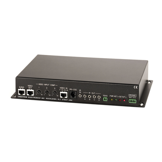
FTP site). Physical Description The CNXRMCLV is housed in a black enclosure with labeling on the front and rear panels. Controls and LED indicators are located on the front panel; connections are made to the front and rear panels. The unit can be mounted in any convenient orientation. - Page 8 5.75 in (14.60 cm) Front Panel VIDEO INPUT COMP VIDEO 1.94 in AUDIO (4.93 cm) Rear Panel 4 • Room Solution Box with Local Video: CNXRMCLV 11.00 in (27.94 cm) 11.60 in (29.46 cm) VIDEO IN RS-232 1-2-3-4 IR OUT...
- Page 9 Crestron CNXRMCLV Input and Output Ports Connections to the CNXRMCLV are made through the ports on the front and rear panels. Refer to the illustrations and descriptions, which follow. AUDIO The RJ-45 AUDIO port is used to transmit and receive analog stereo audio from the head end.
-
Page 10: Led Indicators
IR IN / IR OUT The CNXRMCLV provides one infrared (IR) input, which is a mini phone jack that can connect to a Crestron IR detector (CNXRMIRD) to detect fixed low frequency (38 KHz) IR formats generated by most universal remote control transmitters. This port supports RC5 IR control and some IR control codes from Sharp Electronics Corporation. -
Page 11: Industry Compliance
Video Routing Audio Routing Industry Compliance As of the date of manufacture, the CNXRMCLV has been tested and found to comply with specifications for CE marking and standards per EMC and Radiocommunications Compliance Labelling. NOTE: This device complies with part 15 of the FCC rules. Operation is subject to... -
Page 12: Setup
NOTE: When installing network wiring, refer to the latest revision of the wiring diagram(s) appropriate for your specific system configuration, available from the Downloads | Product Manuals | Wiring Diagrams section of the Crestron website (www.crestron.com). When calculating the wire gauge for a particular network run, the length of the run and the power factor of each network unit to be connected must be taken into consideration. -
Page 13: Mounting
SIMPL Windows procedure. Refer to the note on page 26 for a The Net ID of the CNXRMCLV has been factory set to 42. The Net IDs of multiple definition of Viewport. CNXRMCLVs in the same system must be unique. Net IDs are changed from a personal computer (PC) via the Crestron Viewport. -
Page 14: Video Input Compensation
Video Input Compensation After the system is connected, it may be necessary to adjust the video input compensation pots on the CNXRMCLV to achieve the best picture on the monitor. This requires a narrow slotted screwdriver and an audio/video calibration DVD (or laser disc). - Page 15 CNX-PAD8 (PAD8), then passed through a Crestron amplifier (CNAMPX), and delivered as speaker level audio to the local set of speakers. Analog audio can be directed from the CNXRMCLV back to the BIPAD8 directly, via CAT5, for further distribution. LOCAL SOURCES Operations Guide –...
- Page 16 Distribution of both Analog and Digital Audio to/from the Head End This scenario is identical to the first, except that the CNXRMCLV also allows the user to choose digital audio as a video source from the head end. In the room, the digital audio is sent to a third party surround sound receiver and distributed to the local speakers.
- Page 17 COMPOSITE COMPOSITE S-VIDEO S-VIDEO COMPONENT COMPONENT CNXRMCLV IR/RS-232 CONTROL DIGITAL AUDIO CNXMIRD CLOSURE UNIVERSAL REMOTE Room Solution Box with Local Video: CNXRMCLV • 13 CRESNET CNX-BIPAD8 SOURCE AUDIO DEVICES BALANCED HEAD END ROOM TV or VIDEO PROJECTOR 120 VAC CNXRMCS...
-
Page 18: Recommended Audio/Video Input Configurations
Any universal remote transmitting RC5 code (and some Sharp codes) can communicate with the CNXRMCLV and allow the user to select and activate any function in the control system. An RC5 code is 14 bits long. Each code includes a 5-bit address (or system) and a 6-bit command. -
Page 19: Code Verification
SIMPL Windows program that includes the CNXRMCLV (at the proper Net ID so that the CNXRMCLV can be polled) and a CNXRMIRD. (For details on including the CNXRMIRD in the program, refer to “Receiver”... - Page 20 DVD, AUX). Typically, those buttons are used when setting up the remote with an acceptable code (refer to "Code Verification" on page 15). If an acceptable code is transmitted during that procedure, Crestron assigns the code with an identifier in the "Transmitter Identification" window. For example, in the window shown below, the Transmitter ID (Hex): field shows the number 13.
-
Page 21: Programming Software
This custom template can then be used by Crestron Appbuilder to create the final project files to be loaded into the panels. Alternatively, VT Pro-e can be used to tweak projects created with the Crestron AppBuilder or develop original touchpanel screen designs. -
Page 22: Programming With Crestron Appbuilder
It provides a well-designed graphical environment with a number of workspaces (i.e., windows) in which a programmer can select, configure, program, test, and monitor a Crestron control system. SIMPL Windows offers drag and drop functionality in a familiar Windows This section describes a sample SIMPL Windows program that includes a CNXRMCLV. -
Page 23: C2Net-Device Slot In Configuration Manager
Expanded PRO2 System Tree C2Net-Device Slot in Configuration Manager To incorporate a CNXRMCLV into the system, drag the CNX-RMCLV from the Cresnet Control Modules | Cresnet Video Modules folder of the Device Library and drop it in System Views. The PRO2 system tree displays the unit in Slot 9, with a default Net ID of 42 as shown in the following illustration. - Page 24 Slot 1: Built-in 4 Port IR Card This slot can contain up to four IR devices, selected from the Crestron or User IR Databases. The actual symbols associated with this slot vary depending on the devices in the system.
- Page 25 2. Then, from the Wireless Remotes (IR) folder, drop the Pronto/RC5/Universal IR Remote symbol onto the CNXRMIRD. NOTE: You must use a Crestron IR receiver. Third party receivers are not supported or compatible. The symbol, shown below, consists of a number of outputs (presses), which correspond to the actual buttons on the transmitter.
- Page 26 Break characters are sent out the port separated by the specified pace parameter. RTS is an output from the program to the CNXRMCLV RS-232 port when the state of the RTS line is set. The CNXRMCLV RS-232 port is capable of receiving complex serial data in the form of s erial data s trings on this input line.
- Page 27 (both transmitted and received strings). Slot 6: Audio/Video Matrix Control The CNXRMCLV provides a built-in 8x8 matrix switcher, represented by the Audio/Video Matrix Control symbol. The <Video-Out> analogs specify the video source for an output as follows: the signal is set (typically via an Analog Initialize symbol using decimal (D) format) to a value that corresponds to the video source.
- Page 28 (0% = full left; 100% = full right). Likewise, 50% indicates a neutral level for <Treble> and <Bass>. Audio Settings Symbol 24 • Room Solution Box with Local Video: CNXRMCLV Crestron CNXRMCLV Operations Guide - DOC. 8161A...
-
Page 29: Example Program
Crestron provides five modules for the CNXRMCLV that can be incorporated into programs. For detailed information about the function of a module, select it and press <F1> to review its Help file. These modules are located in the Crestron Database and are named as follows: The Option 1, 2, and 3 modules focus on specific functionality and require different cabling configurations to the Video Out RCA connectors A –... -
Page 30: Communication Settings
The following sections define how one would upload a SIMPL Windows program or upgrade the firmware of the CNXRMCLV. However, before attempting to upload or upgrade, it is necessary to establish communications. Communication Settings NOTE: For laptops and other PCs without a built-in RS-232 port, Crestron recommends the use of PCMCIA cards, rather than USB-to-serial adapters. - Page 31 (115200, N, 8, 1) and necessary options from the “Port Settings” window are selected as shown after this step. Click the OK button to save the settings and close the window. Room Solution Box with Local Video: CNXRMCLV • 27...
-
Page 32: Uploading A Simpl Windows Program
NOTE: Refer to the respective Operations Guide for the control system for details about the other fields shown on the “Send Program” window. 28 • Room Solution Box with Local Video: CNXRMCLV 4. To verify communication, select Diagnostics | Establish Communications (Find Rack). -
Page 33: Firmware Upgrade
“Send Program” Window Firmware Upgrade A firmware upgrade file has the To take advantage of all the CNXRMCLV features, it is important that the unit extension upz. contains the latest firmware available. Therefore, please check the Crestron website (http://www.crestron.com/downloads/software_updates.asp) for the latest version of firmware. - Page 34 File Transfer | Update Control System Command 30 • Room Solution Box with Local Video: CNXRMCLV 1. Apply power to the CNXRMCLV either via Cresnet, with no control system on the network, or directly via a Crestron power supply. 2. Establish communication between the PC and the CNXRMCLV by performing steps 1 through 3 of the procedures given in Communication Settings which begins on page 26.
- Page 35 Crestron CNXRMCLV “Update Control System” Window NOTE: The CNXRMCLV does not have any SIMPL or SIMPL+ modules. Selecting Yes will not affect the program or the device. Operations Guide – DOC. 8161A Room Solution Box with Local Video 5. To upload new firmware, select the file with the “r” suffix (e.g., “51263r.upz) as shown in the illustration below.
-
Page 36: Problem Solving
Room Solution Box with Local Video Problem Solving Troubleshooting The table below provides corrective action for possible trouble situations. If further assistance is required, please contact a Crestron customer service representative. CNXRMCLV Troubleshooting CNXRMCLV does not function. PWR LED does not illuminate. -
Page 37: Further Inquiries
For assistance in your local time zone, refer to the Crestron website (www.crestron.com) for a listing of Crestron worldwide offices. You can also log onto the online help section of the Crestron website (www.crestron.com) to ask questions about Crestron products. First-time users will need to establish a user account to fully benefit from all available features. -
Page 38: Appendix: Mapping Table
Use this table when mapping the buttons on the universal remote. The list can then be used as a reference when creating the SIMPL Windows program. 34 • Room Solution Box with Local Video: CNXRMCLV PHYSICAL DEVICE BEING CONTROLLED: TRANSMITTER ID (HEX):... -
Page 39: Return And Warranty Policies
CRESTRON shall not be liable to honor the terms of this warranty if the product has been used in any application other than that for which it was intended, or if it has been subjected to misuse, accidental damage, modification, or improper installation procedures. - Page 40 Crestron Electronics, Inc. Operations Guide – DOC. 8161A 15 Volvo Drive Rockleigh, NJ 07647 09.03 Tel: 888.CRESTRON Fax: 201.767.7576 Specifications subject to www.crestron.com change without notice.
Need help?
Do you have a question about the CNXRMCLV and is the answer not in the manual?
Questions and answers