Table of Contents
Advertisement
Quick Links
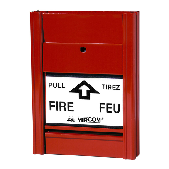
Mircom's MS-400MP(U) Series Fire Alarm Manual Stations
provide manual fire alarm activation. These high quality, extruded
aluminum stations are available as one stage or two stage
stations. On the two stage model, a keyswitch allows the
activation of the stage two alarm. Each station has a permanently
attached MP (Mircom Protocol) addressable module which is
configured with a tool (see LT-6146 MIX-4090 Device
Programmer for instructions).
Specifications & Dimensions
Compatible with Mircom Fire Alarm Control Panels
Electrical Rating:
•
Nominal Operating Voltage: 15-30 VDC
•
Maximum alarm current: 3.3 mA
•
Standby current: 2 mA
Dimensions of aluminum body:
•
4.525" H x 3.3" W x 0.762" D
Notes
• Wire as shown so that supervision of connections is
maintained.
• Maximum wire size: 12 AWG
• All manual fire alarm stations shall be installed as per the
specific requirements outlined in the UL/ULC codes, as well
as all other applicable national or local codes.
• Final acceptance is subject to the local authority having
jurisdiction.
Installing the manual station
This guide covers these models:
•
MS-401MP(U) Intelligent Single Stage Manual Station MP
•
MS-402MP Intelligent Two Stage Manual Station MP
•
MS-407MP(U) Intelligent Single Stage Manual Station MP
with additional N.C. switch
The suffix U indicates a USA version.
Contents of kit
•
MS-401MP(U), MS-407MP(U): 2 mounting screws
•
MS-402MP: 2 mounting screws, 2 stage two keys
Sold separately
•
Plastic rod or break glass (Mircom part number GL-004K)
Canada
25 Interchange Way
Vaughan, ON L4K 5W3
Tel: 1-888-647-2665
1
U.S.A
4575 Witmer Industrial Estates
Niagara Falls, NY 14305
Tel: 1-888-647-2665
MS-400MP(U) Series
Fire Alarm Manual Station
A. Wiring
Note:
The maximum wire size is 12 AWG.
1.
Connect the black (−) wire from the previous station to
the terminal that is connected to the black (−) wire from
the addressable module.
2.
Connect the black (−) wire leading the next station to the
other side of the terminal that is connected to the black
(−) wire from the addressable module.
Note:
The wires must be on opposite sides of the set screw.
Refer to Figure 2 for the location of the wires.
3.
Tighten the (−) terminal.
4.
Connect the red (+) wire from the previous station to the
terminal that is connected to the red (+) wire from the
addressable module.
5.
Connect the red (+) wire leading to the next station to the
other side of the terminal that is connected to the red (+)
wire from the addressable module.
Note:
The wires must be on opposite sides of the set screw.
Refer to Figure 2 for the location of the wires.
6.
Tighten the (+) terminal.
TO NEXT STATION OR END
OF LINE DEVICE
+
−
FROM
−
{
PREVIOUS
+
STATION
AUXILIARY FUNCTION
NORMALLY CLOSED SWITCH
{
(MS-407MP(U) ONLY)
Figure 1: Wiring Diagram
CORRECT: BOTH
WIRES ON
OPPOSITE SIDES
OF THE SET SCREW
X
WRONG: BOTH
WIRES ON THE
SAME SIDE OF
THE SET SCREW
Figure 2: Close-up of terminals showing correct wiring
www.mircom.com LT-6660 Rev. 3 July 2020
−
BLACK
+
RED
ADDRESSABLE
MODULE
TO ADDRESSABLE
MODULE
TO ADDRESSABLE
MODULE
Advertisement
Table of Contents

Related Manuals for Mircom MS-400MP Series


Summary of Contents for Mircom MS-400MP Series
- Page 1 MS-402MP: 2 mounting screws, 2 stage two keys CORRECT: BOTH WIRES ON TO ADDRESSABLE Sold separately MODULE OPPOSITE SIDES • Plastic rod or break glass (Mircom part number GL-004K) OF THE SET SCREW WRONG: BOTH WIRES ON THE TO ADDRESSABLE SAME SIDE OF MODULE Canada U.S.A...
- Page 2 Activating the alarm • Pull down the handle. The handle is now hanging down. A qualified person must reset the station. See Resetting the manual station. Figure 4: Resetting the manual station www.mircom.com LT-6660 Rev. 3 July 2020...
Need help?
Do you have a question about the MS-400MP Series and is the answer not in the manual?
Questions and answers