Table of Contents
Advertisement
Quick Links
PN: 856329 12V 856345 12V 856322 12V 931781 12V
Introduction
Feature
Line pull:
4,082 kg / 9,000 lb wire rope first layer
Wire rope:
8.3 mm × 30.5 m (21/64" × 100') galvanized aircraft A7 × 19
Brake:
Patented cone brake holds full load
Clutch:
Turn the T-handle for rapid wire rope payout
Control:
Handheld pendant switch to power the winch
Unpacking
.Winch assembly...............................................................
.Control box........................................................................
.Remote control................................................................
.Wire rope with clevis hook..................................................
.Roller fairlead..................................................................
.1.8 m ( 6' ) 2 gauge battery lead..........................................
Read this manual carefully
You should carefully read and understand this manual before operating it.
Careless winch operation may result in personal injury hazards or property
damage.
Installation
Before using the winch, make sure all electrical components have no
corrosion or damaged; the environment should be clear and dry.
Winch and roller fairlead mountings
. It is very important that the winch will be mounted
on a flat and hard surface of mounting channel
in order to make sure the motor, drum and
gearbox housing are aligned correctly.
. Roller fairlead does not mount to the winch
directly.
. The wire rope shall be wound in an under-wound orientation only.
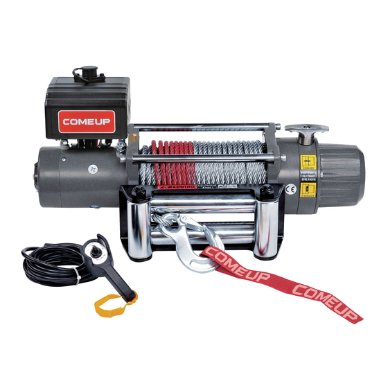
Self-Recovery Winch
DV-9
Model:
856355 24V 931787 24V
1 pc
1 pc
1 pc
1 pc
1 pc
1 pc
. Four (4) M10 x 1.50 pitch 8.8 grade with 44 N-m torque settings (maximum)
high tensile steel bolts must be used in order to sustain the loads imposed
on the winch mounting.
. Two (2) M12 x 1.75 pitch 8.8 grade with 76 N-m torque settings (maximum)
high tensile steel bolts must be used for fastening the roller fairlead into
the mounting channel.
Wiring Diagram
Attach the black lead firmly to the negative (–) battery terminal and red lead
to the positive (+) battery terminal. The voltage drop for the winch motor
must not exceed 10% of the nominal voltage of 12/24V DC.
Nut fastening for motor & contactor
1.Holding the lower nut on the stub and fastening the upper nut clockwise.
2.The torque setting for nut is 14 N-m/124 lb-in.
Warning
.The winch is not intended to be used in any manner for the movement or
lifting of personnel.
. The rated line pull shown is based on the first layer of rope on the drum.
.The rope winding on the drum shall remain 5 wraps from the drum.
Advertisement
Table of Contents

Related Manuals for Comeup DV-9


Summary of Contents for Comeup DV-9
- Page 1 . Four (4) M10 x 1.50 pitch 8.8 grade with 44 N-m torque settings (maximum) high tensile steel bolts must be used in order to sustain the loads imposed on the winch mounting. DV-9 Model: . Two (2) M12 x 1.75 pitch 8.8 grade with 76 N-m torque settings (maximum)
- Page 2 Parts List Winch Assembly Item No. Description Part No. Motor 12V 882153 Motor 24V 883126 Tie bar kit 880003 Tie bar kit for PN:856345 882546 Motor support rack 881779 Motor coupling 880005 Drum bushing 880006 Drum kit 881101 Gearbox support rack 881780 Grounding lead 880009...
Need help?
Do you have a question about the DV-9 and is the answer not in the manual?
Questions and answers