Table of Contents
Advertisement
Quick Links
PN: 641656 12V DC 641504 12V DC 642037 24V DC 641526 12V DC
Introduction
Feature
2,041 kg / 4,500 lb wire rope first layer
Line pull:
Wire rope;
6.3 mm galvanized aircraft A7 × 19
Brake:
Mechanical and dynamic brakes hold full load
Clutch:
Raise the clutch level for rapid wire rope payout
Control:
Handheld pendant switch powers the winch
Unpacking
.Integrated solenoid kit ........................................................... 1 pc
.Remote control .................................................................... 1 pc
.Wire rope with hook 6.3 mm x 15.2 m (1/4" x 50')........................ 1 pc
.Wire rope with hook 5.6 mm X 18 m (7/32"X59') for PN:641504....... 1 pc
.Wire rope with hook 6.3 mmX 10 m (1/4"X33') for PN:641526........ 1 pc
.Roller fairlead...................................................................... 1 pc
.1.5 m battery leads............................................................... 1 pc
.Circuit breaker..................................................................... 1 pc
Read this manual carefully
You should carefully read and understand this manual before operating it.
Careless winch operation may result in personal injury hazards or property
damage.
Information requesting or parts ordering
Please specify the followings information:
.Winch PN
.Serial number
.Quantity for each part
Installation
Before using the winch, make sure all electrical
components have no corrosion or damaged; the
environment should be clear and dry.
The voltage drop must not exceed 10% of the
nominal voltage of 12V or 24V under normal
operation condition.
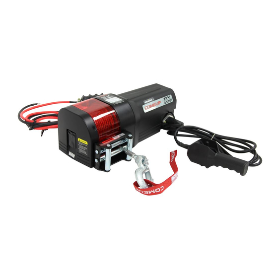
Utility Duty Winch
DV-4500i
Model:
642015 24V DC 641624 12V DC
642172 24V DC
.Part description
.Replacement part number
Winch and roller fairlead mounting
Use the mounting hardware supplied to mount the winch on a flat
surface.
The motor, drum and gear housing must be properly aligned.
Wiring Diagram
The battery lead specifications for 12V winch are 6 AWG X 1.5 m (5')
and 8 AWG X 1.5 m (5') for 24V winch respectively.
Use a 5/16" bolt, nut and washer to attach the firmly to the bolts of
solenoid respectively.
Attach the red lead, positive (+), tightly to the circuit breaker marked AUX,
meanwhile, connect the copper plate to the other end of the circuit
breaker marked BAT.
Connect the copper plate to the connector of the battery.
Nut fastening for motor & solenoid
1.Holding the lower nut on the stub and fastening the upper nut clockwise.
2.The torque setting for motor nut M6 is 5.7 N-m / 50 lb-in and solenoid nut
M8 is 14 N-m / 124 lb-in.
Advertisement
Table of Contents

Related Manuals for Comeup DV-4500i


Summary of Contents for Comeup DV-4500i
- Page 1 Winch and roller fairlead mounting Utility Duty Winch Use the mounting hardware supplied to mount the winch on a flat DV-4500i Model: surface. The motor, drum and gear housing must be properly aligned. PN: 641656 12V DC 641504 12V DC 642037 24V DC 641526 12V DC ...
- Page 2 Warning Winch Assembly The winch is not intended to be used in any manner for the movement or lifting of personnel. The pulling capacity shown is based on the wire rope first layer on the drum. The rope winding on the drum shall remain 5 wraps from the drum. Parts List Item No.
Need help?
Do you have a question about the DV-4500i and is the answer not in the manual?
Questions and answers