
Subscribe to Our Youtube Channel
Related Manuals for cias SIOUX


Summary of Contents for cias SIOUX
- Page 1 SIOUX Sistema di protezione recinzioni Manuale d’installazione Fence Protection System Installation manual Edizione / Edition 1.6 20MACIE0220...
-
Page 2: Table Of Contents
INDICE 1. DESCRIZIONE ................................4 1.1 D ............................4 ESCRIZIONE DEL SISTEMA 2. INSTALLAZIONE ................................. 5 2.1 I ............................5 NFORMAZIONI PRELIMINARI 2.2 I ............................6 NSTALLAZIONE DEI SENSORI 2.3 I -CU ............................ 7 NSTALLAZIONE DI IOUX 2.4 C ..........................7 ONFIGURAZIONE DEL SISTEMA 3. - Page 3 INDEX 1. DESCRIPTION ................................24 1.1 S ..............................24 YSTEM ESCRIPTION 2. INSTALLATION ................................25 2.1 I ..............................25 NITIAL NFORMATION 2.2 S ............................... 26 ENSOR INSTALLATION 2.3 I -CU ..........................27 NSTALLATION OF THE IOUX 2.4 S ............................27 YSTEM CONFIGURATION 3.
-
Page 4: Descrizione
Sioux è un sistema di protezione perimetrale per reti e/o recinzioni. E’ costituito da un’unità di elaborazione (Sioux-CU), la quale ha in gestione due linee di sensori (fino a 70 per linea: 10 master e 60 slave) che, una volta collegati alla recinzione perimetrale, sono in grado di rilevare le perturbazioni causate da tentativi di intrusione per scavalcamento o taglio della recinzione stessa. -
Page 5: Installazione
Tenere conto della distanza a cui disporre i sensori. Questo è necessario per sapere di quante Sioux-Master e Sioux-Slave si avrà bisogno e della lunghezza dei cavi per il collegamento dei sensori. I cavi possono aver lunghezza 3 m, 5 m o 10 m. Il cavo è resistente ai raggi UV ed alle intemperie. -
Page 6: Installazione Dei Sensori
La freccia del contenitore schermato in cui è alloggiata una scheda master, indica la direzione dove si trova la Sioux-CU. La Sioux Master si differenzia dalle Sioux Slave tramite un bollino verde posto al centro del contenitore schermato. Se invece si tratta di una scheda slave la freccia indica la relativa Master. -
Page 7: Installazione Di Sioux-Cu
2.4 Configurazione del sistema Per la configurazione del sistema utilizzare il programma “Sioux test”. E’ possibile dividere il sistema globale in più sottosistemi costituiti da una Sioux-CU, 20 master e 120 slave per un totale di 140 sensori. Ogni sottosistema può essere poi suddiviso in massimo di 20 zone ed ad ogni zona attribuire tutte le caratteristiche volute ( soglia di allarme intrusione, soglia di allarme taglio, ecc ). -
Page 8: Collegamenti
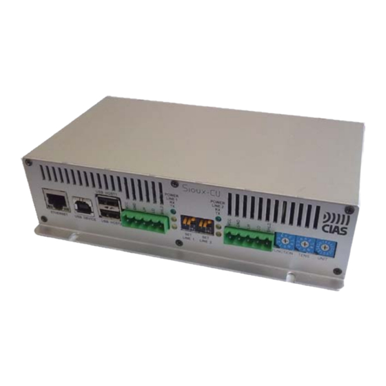
Ha un orologio interno che consente di avere la data e l’ora con la definizione del secondo. Sioux-CU può essere alimentato con una tensione di 13,8V da un alimentatore oppure attraverso una rete Ethernet dotata di Power over Ethernet (PoE). (Opzione) Sioux-CU è... - Page 9 Ed 1.6 Sul frontalino anteriore sono presenti partendo da sinistra: 1 connettore Ethernet con possibilità di alimentare Sioux-CU con PoE (ETHERNET) 1 connettore USB device (USB DEVICE) 1 connettore con doppia porta USB Host (USB HOST1 e USB HOST2) NON ATTIVO...
- Page 10 1 Jack audio (AUDIO) NON ATTIVO. 1 Pulsante (SET BUTTON) 1 morsettiera seriale RS485 per la connessione della Sioux-CU all’IB-System R o alla scheda relè (LINE3) 3 led relativi alla seriale LINE3: partendo dall’alto un led verde che indica la presenza di...
-
Page 11: Descrizione Funzioni
- 1: attribuzione automatica del number device delle schede Sioux-master - 2: assegnazione del numero di Sioux-CU - 3: attribuzione manuale del number device delle schede Sioux-master presenti sul ramo sinistro - 4: attribuzione manuale del number device delle schede Sioux-master presenti sul ramo destro - 5: configurazione delle zone con la procedura “Touch and Zone”... -
Page 12: Assegnazione Automatica Del Number Device
Durante l’esecuzione di questa procedura vengono assegnati automaticamente i number device ai vari dispositivi Sioux-Master connessi alle due linee seriali LINE1 e LINE2. A partire dai dispositivi Sioux-Master più vicini su entrambe le linee seriali vengono assegnati i number device 4, 11, 18, 25, 32, 39, 46, 53,60, 67. -
Page 13: Touch And Zone
− Il primo sensore colpito identifica l’inizio della prima zona e deve coincidere con l’ultimo sensore configurato del ramo sinistro (il primo è il sensore più vicino alla Sioux CU). Colpire quindi l’ultimo sensore del ramo sinistro, il buzzer della Sioux-CU emetterà un segnale acustico a conferma dell’avvio della procedura. -
Page 14: Modifica Numero Sensori Del Ramo Sinistro
© CIAS Elettronica S.r.l. Ed 1.6 3.2.1.5 Modifica numero sensori del ramo sinistro Per modificare il numero di sensori del ramo sinistro posizionare il commutatore delle funzioni su 6 ed i commutatori decine e unità in modo da comporre il numero di sensori presenti ed installati sul ramo sinistro. -
Page 15: Sioux-Master
3.3 Sioux-Master La scheda Sioux-Master comunica con Sioux-CU attraverso un canale seriale RS485. Risponde al polling generato da Sioux-CU e trasmette i segnali del sensore presente a bordo più quelli di altri sei sensori a bordo di altrettante schede Sioux-Slave. -
Page 16: Sioux-Slave
CIAS Elettronica S.r.l. Ed 1.6 3.4 Sioux-slave Sioux-slave è una scheda che ha la caratteristica di avere un sensore a bordo. 6 schede slave fanno riferimento ad una scheda master. La scheda master acquisisce i segnali dei sensori presenti sulle schede slave di sua competenza e comunica i segnali ricevuti a Sioux-CU in formato digitale. -
Page 17: Descrizione Dei Collegamenti
© CIAS Elettronica S.r.l. Ed 1.6 3.6 Descrizione dei collegamenti Nella figura sottostante sono rappresentati i collegamenti di un sistema Sioux. Manuale d’installazione Page 17 of 43 Sioux... - Page 18 Marrone Schermo Schermo Schermo - Cavo di connessione tra la seriale (LINE1 o LINE2) di Sioux-CU e la prima Sioux-slave N.B. Utilizzando cavi precablati, verificare la corrispondenza dei colori con la numerazione dei pin del connettore RJ45. Moretto Connettore Pin Connettore RJ45 Sioux Slave...
- Page 19 © CIAS Elettronica S.r.l. Ed 1.6 - Connessioni di alimentazione - Cavo del tamper - Cavo di connessione ethernet - Cavo cross modello EL EIA/TIA568A/B (8pin) - Cavo USB Manuale d’installazione Page 19 of 43 Sioux...
- Page 20 CIAS Elettronica S.r.l. Ed 1.6 Nel caso in cui Sioux-CU debba essere posizionato lontano dai sensori si può utilizzare una scatola di derivazione a cui collegare i due rami dei sensori e un cavo per ciascuna linea (Lead cable), che porta i segnali e l’alimentazione dalla Sioux-CU.
- Page 21 Bianco/Arancio, Arancio, e Bianco/Verde assieme al conduttore BLU a GND cioè al morsetto 2 della morsettiera Sioux CU. Verde e Bianco/blu a Vcc cioè al morsetto 1 della morsettiera Sioux CU. - cavo scatola di derivazione primo Sioux-slave N.B. Utilizzando cavi precablati, verificare la corrispondenza dei colori con la numerazione dei pin del connettore RJ45.
-
Page 22: Ricerca Guasti
© CIAS Elettronica S.r.l. Ed 1.6 4. Ricerca guasti Difetto Possibile Causa Possibile Soluzione L’indicatore GENERAL POWER Guasto alimentatore Verificare con uno strumento che si spegne. l’alimentatore funzioni correttamente. Batteria scarica Verificare il livello di carica della batteria e lo stato dell’alimentazione di rete. -
Page 23: Caratteristiche
CIAS Elettronica S.r.l. Ed 1.6 5. Caratteristiche 5.1 Sioux Caratteristiche tecniche SIOUX Unit Tensione di alimentazione Sioux-CU (V~) Tensione di alimentazione Sioux-Controller (V ) 11.0 13.8 17.0 Tensione di alimentazione Sioux-master (V ) 13.8 Tensione di alimentazione Sioux-slave (V ) 13.8... - Page 24 Sioux is a perimeter protection system for fences and/or other structures. It comprises a central control board (Sioux-CU), which can manage two lines of sensors (up to 70 per line: 10 master and 60 slave) that, when mounted on a perimeter fence, are able to detect the disturbances caused by attempts to climb or cut the fence.
- Page 25 Decide on the mounting distance between sensors. This is necessary to calculate the number of Sioux-Master and Sioux-Slave that will be required and the lengths of the sensor interconnecting cables. The cables can have a length of 3, 5 or 10m and it is resistant to UV and weather.
- Page 26 The screened containers have an arrow marked on the cover which is used during the installation. If the unit is a master the arrow indicates the direction in which it will find the Sioux-CU. If the unit is a Slave the arrow indicates the direction of the associated Master.
- Page 27 2.3 Installation of the Sioux-CU The Sioux-CU control unit is mounted in a special container which also houses the battery and power supply. To this will be connected the left and right sensor branches, the power, the container tamper and possibly an RS485 serial cable for connection to an IB System R.
- Page 28 It has an internal clock for date and time with a resolution of 1 second.. Sioux-CU can be powered from 13.8V by a suitable power supply or using an Ethernet network with Power over Ethernet (PoE). (Option)
- Page 29 Ed 1.6 On the front plate, from the left are: 1 Ethernet connector with the possibility of power to the Sioux-CU via PoE (ETHERNET) 1 USB device connector (USB DEVICE) 1 connector with a double USB Host port (USB HOST1 and USB HOST2) not active.
- Page 30 1 Audio Jack (AUDIO) actually not active. 1 Push button (SET BUTTON) 1 RS485 serial terminal block for the connection of the Sioux-CU to the IB-System or to the relay cards (LINE3) 3 led associated with serial LINE3: from the top a green led which indicates the presence...
- Page 31 - 1: automatic assignment of the device numbers of the Sioux-master boards - 2: allocation of the number of the Sioux-CU - 3: manual assignment of the Sioux-master device numbers present on the left branch - 4: manual assignment of the Sioux-master device numbers present on the right branch - 5: zone configuration with “touch and zone”...
- Page 32 Starting from the closest Sioux-Master device on both lines they will be assigned device numbers 4, 11, 18, 25, 32, 39, 46, 53,60, 67. Once the device number assignment is finished the position of the Sioux-CU will be read and stored (Reference Position).
- Page 33 To activate the “Touch and Zone” position the function switch on 5 and push then SET BUTTON. Take care that the configured sensors number is equal to the sensors connected to Sioux CU. If after the last master on a branch there aren’t 3 slave sensors, modify the sensors number of that branch.
- Page 34 Sioux-Slaves. For each serial connection on the Sioux-CU it is possible to connect up to 10 Sioux-Master, each with an address different from the others. The addresses assigned to the Sioux-Masters depends on the order in which they are connected along the serial line and can have the values of 4, 11,18, 25, 32, 39, 46, 53, 60, and 67.
- Page 35 Ed 1.6 3.4 Sioux-slave Sioux-slave is a board whose only function is to have a sensor on board. 6 slave boards can connect to a master board. The master board acquires the signals of the sensors present on the slave boards under its control and communicates these received signals to the Sioux-CU in digital format.
- Page 36 © CIAS Elettronica S.r.l. Ed 1.6 3.6 Description of the connections The following figure shows the connections for a typical Sioux system. Installation Manual Page 36 of 43 Sioux...
- Page 37 Brown Shell Shield Shield Shield - Connection cable between serial lines (LINE1 or LINE2 ) of the Sioux-CU and first Sioux-slave REMARK: Using only precabled cable, check that colors correspond to numbering of RJ45 connector’s pin. Pin RJ45 Function Terminal Block...
- Page 38 © CIAS Elettronica S.r.l. Ed 1.6 - Power and battery connections - Tamper cable - Ethernet connection cable Connector Connector Ethernet Ethernet Connector Connector - Cross Cable model EL EIA/TIA568A/B (8pin) USB cable Connector Connector Type A Type B Installation Manual...
- Page 39 CIAS Elettronica S.r.l. Ed 1.6 When the Sioux-CU must be located at long distance away from the sensors it is necessary to use a distribution box to which the two sensor branches are connected, together with a cable (each one), which carries the signals and power to/from the Sioux-CU.
- Page 40 Connect White/Orange, Orange, White/Green, and Blue wires together to terminal 2 (GND) of the Sioux CU terminal block. Connect Green and White/Blue wires together to terminal 1 (Vcc) of the Sioux CU terminal block. - Cable between junction box and first Sioux-slave...
- Page 41 IB-System (when connected to IB System) Yellow Indicator TX for LINE3 Configuration not set correctly Check configuration with Sioux not flashing Test (when connected to IB System) Acquisition of the field Make field acquisition on IB configuration by the IB System...
- Page 42 CIAS Elettronica S.r.l. Ed 1.6 5. Characteristics 5.1 Sioux Technical Characteristics Unit Power supply Voltage Sioux-CU (V~) Power supply Voltage Sioux-Controller (V ) 11.0 13.8 17.0 Power supply Voltage Sioux-master (V ) 13.8 Power supply Voltage Sioux-slave (V ) 13.8...
- Page 43 © CIAS Elettronica S.r.l. Ed 1.6 NOTE: Installation Manual Page 43 of 43 Sioux...
- Page 44 At the end of operative life the product can be given back to the vendor/installation organization in occasion of a new purchase. © Copyright CIAS Elettronica S.r.l. Stampato in Italia / Printed in Italy CIAS Elettronica S.r.l. Direzione, Ufficio Amministrativo, Ufficio Commerciale, Laboratorio di Ricerca e Sviluppo Direction, Administrative Office, Sales Office, Laboratory of Research and Development 20158 Milano, via Durando n.
Need help?
Do you have a question about the SIOUX and is the answer not in the manual?
Questions and answers