Table of Contents

Related Manuals for cias ERMO 482


Summary of Contents for cias ERMO 482
- Page 1 ERMO 482 Barriera a Microonde per protezioni interne ed esterne Manuale di Installazione Internal and external Microwave protection Barrier Installation Handbook Edizione / Edition 2.2...
-
Page 2: Table Of Contents
CIAS Elettronica S.r.l. Ed. 2.2 INDICE 1. DESCRIZIONE ..................................3 1.1 D ..................................3 ESCRIZIONE 1.2 S ................................4 CHEMA A LOCCHI 2. INSTALLAZIONE .................................. 5 2.1 I ..............................5 NFORMAZIONI PRELIMINARI 2.2 N ................................6 UMERO DI RATTE 2.3 C... - Page 3 CIAS Elettronica S.r.l. Ed. 2.2 INDEX 1. DESCRIPTION ..................................24 1.1 D ..................................24 ESCRIPTION 1.2 B ................................25 LOCK IAGRAM 2. INSTALLATION .................................. 26 2.1 P ............................26 RELIMINARY NFORMATIONS 2.2 N ............................... 27 UMBER OF ECTIONS 2.3 G ................................
-
Page 4: Descrizione
1. DESCRIZIONE 1.1 Descrizione ERMO 482 è la barriera a microonde di CIAS per protezione volumetrica interna ed esterna. Il suddetto sistema è in grado di rilevare la presenza di un corpo che si muove all’interno di un campo sensibile instauratosi tra il Trasmettitore (TX) e il Ricevitore (RX). -
Page 5: Schema A Blocchi
1.2 Schema a Blocchi Negli schemi a blocchi che seguono sono rappresentati i gruppi funzionali del circuito Trasmettitore e del circuito Ricevitore della barriera Ermo 482. Schema a Blocchi circuito Trasmettitore Ermo 482 Schema a Blocchi circuito Ricevitore Ermo 482... -
Page 6: Installazione
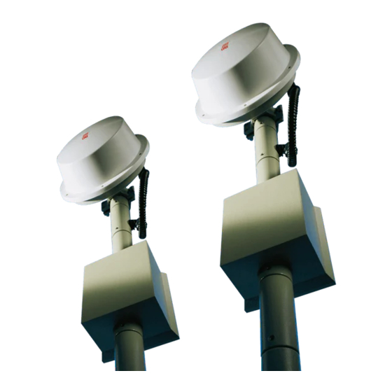
Ed. 2.2 2. INSTALLAZIONE 2.1 Informazioni preliminari Nella figura sotto riportata è indicato un rivelatore Ermo 482 completo di accessori: palo ( diviso in tronchetti ), scatola di derivazione, ganasce e radiale per ancoraggio al terreno. Manuale di Installazione Pagina 5 di 43... -
Page 7: Numero Di Tratte
CIAS Elettronica S.r.l. Ed. 2.2 2.2 Numero di Tratte Dovendo progettare la protezione con barriere volumetriche di un perimetro chiuso, oltre alle normali considerazioni di suddivisione del perimetro in un certo numero di tratte che tengano conto delle necessità gestionali dell'intero impianto, occorre ricordare che è sempre preferibile installare un numero di tratte pari. -
Page 8: Condizioni Del Terreno
CIAS Elettronica S.r.l. Ed. 2.2 2.3 Condizioni del Terreno E' sconsigliabile installare gli apparati lungo tratti dove vi sono: erba alta (maggiore di 10 cm), stagni, corsi d'acqua in senso longitudinale ed in generale tutti quei tipi di terreni la cui conformazione sia rapidamente variabile. -
Page 9: Ampiezza Dei Fasci Sensibili
S ensibilità m inim a lunghezza della tratta (m ) Figura 3 - Diametro della zona sensibile a metà tratta, in spazio libero, per ERMO 482/ 50 Diam etro a m età tra tta (m ) S ensibilità m assim a S ensibilità... -
Page 10: Lunghezza Delle Zone Morte In Prossimità Degli Apparati
Zona Morta (m) Figura 5 - Lunghezza della zona morta in prossimità degli apparati in funzione dell’altezza dal centro degli stessi al suolo per ERMO 482/. 50 Alte zza da l suolo de gli a pp a ra ti (c m ) Se nsibilità... -
Page 11: Collegamenti
Faston Rosso Al Positivo di Batteria Figura 8 Disposizione topografica dei componenti nel circuito Tx Nelle seguenti tabelle sono indicate le funzioni delle morsettiere, connettori, selettori e trimmer presenti sulla scheda ERMO 482 TX: MORSETTIERA MS1 TRASMETTITORE Mors. Simbolo Funzione... - Page 12 CIAS Elettronica S.r.l. Ed. 2.2 CONNETTORE DI MISURA PER STC 95 TRASMETTITORE Mors. Simbolo Funzione 13,8 Tensione di alimentazione 13,8 V Negativo della tensione di alimentazione ( 0 V ) Segnale funzionamento Oscillatore ( 4,5 V Alimentazione interna 9 V LEDS DEL TRASMETTITORE N°...
-
Page 13: Circuito Ricevitore
Faston Rosso Al Positivo di Batteria Figura 9 Disposizione topografica dei componenti nel circuito Rx Nelle seguenti tabelle sono indicate le funzioni delle morsettiere, connettori, selettori e trimmer presenti sulla scheda ERMO 482 TX: MORSETTIERA MS1 - RX Mors Simbolo... - Page 14 CIAS Elettronica S.r.l. Ed. 2.2 CONNETTORE DI MISURA PER STC 95 RICEVITORE Mors Simbolo Funzione 9 V Soglia di Allarme ( 0,3 V Segnale di barriera in Allarme Segnale rivelato normalmente 0 V Verifica segnale amplificato ( 200 mVpp )
-
Page 15: Collegamento All'alimentazione Principale
CIAS Elettronica S.r.l. Ed. 2.2 3.2 Collegamento all’Alimentazione Principale Gli apparati pur funzionando perfettamente in Corrente Continua a 13,8 V , è preferibile che siano alimentati in corrente Alternata alla tensione di 19 V~. 3.2.1 Collegamento all’Alimentazione Il collegamento tra il trasformatore e la rete a 230 V~ dovrà essere effettuato con conduttori la cui sezione sia di almeno 1,5 mm². -
Page 16: Collegamento Alla Centrale
Nelle protezioni ad Alto Rischio è indispensabile che i rivelatori siano sottoposti con adeguata periodicità al Test Operativo. In questo modo la centrale di allarme sarà in grado di riconoscere i tentativi di elusione. Per effettuare il Test operativo della barriera Ermo 482 utilizzare l’accessorio Ermo-Test o disalimentare il trasmettitore. -
Page 17: Allineamento E Verifica
4. ALLINEAMENTO E VERIFICA 4.1 Allineamento e Verifica con Strumento STC 95 Per l’allineamento e la taratura delle proprie barriere, CIAS ha realizzato uno strumento che facilita tali operazioni ed è quindi un valido supporto per gli installatori. Di seguito è... -
Page 18: Operazioni Sul Trasmettitore
Connessioni dello strumento STC 95 con le barriere ERMO 482 CIAS Figura 11 4.1.1 Operazioni sul Trasmettitore Per effettuare la taratura e il collaudo del Trasmettitore ERMO 482 occorre procedere nel seguente modo: 1. togliere la calotta di policarbonato ( Radome ) svitando le apposite viti;... -
Page 19: Operazioni Sul Ricevitore
CIAS Elettronica S.r.l. Ed. 2.2 5. Effettuare l’interconnessione tra lo strumento STC 95 e la barriera ERMO 482 TX, come indicato in figura 11, inserendo il connettore a 4 pin nel “connettore di misura” del circuito. a) Verificare che il led ”Rx/Tx 1” (22) sia acceso. Qualora fosse spento premere il tasto “1”... - Page 20 CIAS Elettronica S.r.l. Ed. 2.2 e) Premere il tasto ”” (10) fino ad ottenere l’accensione del led “field Rx” (5). 10 % e sulla barra a Verificare che sul display sia leggibile una tensione di circa 6 V led (3) sia acceso il led centrale.
- Page 21 CIAS Elettronica S.r.l. Ed. 2.2 Una Sensibilità troppo elevata può causare allarmi impropri. Si consiglia di non adottare sensibilità maggiori del 75 % (corsa del trimmer) che corrisponde a circa 1,6 V Una Sensibilità troppo bassa può impedire la rivelazione di un intruso di dimensioni ridotte.
- Page 22 CIAS Elettronica S.r.l. Ed. 2.2 s) Lo strumento STC 95, come mostrato in fig.11 dispone di un’uscita RCA (23) che, mediante il cavetto in dotazione, consente di verificare la forma d’onda del segnale ricevuto. Tale verifica richiede un oscilloscopio (qualsiasi modello presente sul mercato).
-
Page 23: Manutenzione E Assistenza
CIAS Elettronica S.r.l. Ed. 2.2 5. MANUTENZIONE E ASSISTENZA 5.1 Ricerca Guasti In caso di Falsi Allarmi, verificare i parametri riscontrati durante l’Installazione che saranno stati registrati nell’apposita Scheda di Collaudo allegata e se si riscontrano delle variazioni che eccedono i limiti indicati, rivedere i relativi punti nel capitolo 4 “... -
Page 24: Caratteristiche
In accordo con le richieste nazionali Modulazione On / Off Duty-Cycle 50 / 50 Numero di canali PORTATE ERMO 482 / 50 50 m ERMO 482 / 80 80 m ERMO 482 / 120 120 m ERMO 482 / 200... - Page 25 1. DESCRIPTION 1.1 Description The ERMO 482 equipment is a microwave system for outdoor / indoor volumetric barrier protection. Such a system can detect the presence of somebody or something moving within the sensitive field present between the transmitter (Tx) and the receiver (Rx).
- Page 26 CIAS Elettronica S.r.l. Ed. 2.2 1.2 Block Diagram In the following diagrams are showed the functional block of the complete Ermo 482 (Transmitter and Receiver). Modula tor Channel B attery Freguency Select Generator Ermo 482 Transmitter Block Diagram B attery...
- Page 27 2. INSTALLATION 2.1 Preliminary Informations Due to the various types of ERMO 482 barrier, there are some different kinds of installation and fixing unit types related to user requirements. The following picture show ERMO 482 device with accessories: pole segment, transformer junction box, pole bracket and anti-spin bars.
- Page 28 CIAS Elettronica S.r.l. Ed. 2.2 2.2 Number of Sections Having to design protection with volumetric barriers of a closed perimeter, besides having to split the perimeter within a certain number of sections that take into account the management need of the entire plant, it must be remembered that it is always preferable to install an even number of sections.
- Page 29 CIAS Elettronica S.r.l. Ed. 2.2 2.3 Ground conditions It is inadvisable to install the equipment along sections with tall grass (more than 10 cm), ponds, longitudinal waterways, and all those types of grounds whose structure is rapidly mutable. 2.4 Presence of Obstacles...
- Page 30 (Free space) Remark: that for the ERMO 482 equipment, the Sensitivity regulation to be considered for obtaining the dimensions of the sensitivity beams half-way of the section, is that of the alarm threshold. The higher the threshold the lower the sensitivity, and vice versa.
- Page 31 Height (cm ) Ma xim um Minim um Sensitivity Sensitivity Length of the Dea d Zone Figure 5 ERMO 482 -50: Dead zone length near the equipment versus installation height. Installation Height (cm) Ma xim um Minim um Sensitivity Sensitivity...
- Page 32 3. CONNECTIONS 3.1 Terminal Blocks, Connectors and Circuits Functions 3.1.1 Transmitter Circuit The following figure and tables show the terminal block and connector function present on the ERMO 482 TX board. 4 3 2 1 B ulb T a mper...
- Page 33 CIAS Elettronica S.r.l. Ed. 2.2 TRASMITTER TEST CONNECTOR FOR STC 95 INSTRUMENT Term Symbol Function 13,8 Power Supply 13,8 V Ground Function Oscillator Signal OK ( 4,5 V Internal Power Supply 9 V TRASMITTER LEDS N° Symbol Function Default...
- Page 34 CIAS Elettronica S.r.l. Ed. 2.2 3.1.2 Receiver Circuit The following figure and tables show the terminal block and connector function present on the ERMO 482 RX board. MS 1 SEN. INT . T amper Fuse B ulb DS 1...
- Page 35 CIAS Elettronica S.r.l. Ed. 2.2 RECEIVER TEST CONNECTOR FOR STC 95 INSTRUMENT Term Symbol Function Alarm threshold ( 0,3 9 V Alarm signal Detected signal Amplify signal ( 200 mVpp ) Power Supply Output 13,8 V Ground V Rag...
- Page 36 CIAS Elettronica S.r.l. Ed. 2.2 3.2 Equipment Connection to the Power Supply Even if the equipment is Direct Current powered ( 13,8 V ), they still operate properly, but it is advisable to power it by Alternating Current ( 19 V 3.2.1 Connection to the Power Supply...
- Page 37 CIAS Elettronica S.r.l. Ed. 2.2 3.3 Connection to the Control Panel On transmitter and receiver PCB are present 1 relays. These Relay is static with dry contacts normally closed. By means of these contacts it’s possible to communicate to the control panel the following conditions: Alarm, Tamper 3.3.1 Alarm contacts: Alarm, Tamper...
- Page 38 4. ADJUSTMENT AND TESTING 4.1 Adjustment and Testing with STC 95 Instrument For the Microwave Barrier Adjustment and Testing, CIAS gives the availability of a dedicated instrument, with the intention to facilitate installation operation and operator activity support. The following figure 10 shows the CIAS STC 95 instrument with function explanations.
- Page 39 RCA /BNC Cable Figure 11 4.1.1 Transmitter Setting-up To align and adjust the Transmitter ERMO 482 proceed as follows: - unscrew the specific screws to remove the front cover ( Radome ); - activate the power supply connection to MS1 terminal block;...
- Page 40 4 channels available through the channel selector DS 1, same as channel preset on Transmitter unit. Connect the STC 95 instrument to the ERMO 482 RX barrier as shown in figure 9. Insert the seven pins connector into its connector present on Receiver circuit (fig. 9).
- Page 41 CIAS Elettronica S.r.l. Ed. 2.2 g) Repeat the pointing operation on the horizontal adjustment of the transmitter module. h) After having obtained the best pointing, lock the horizontal movement of the TX and RX modules. i) Unlock the vertical movement of the RX module and direct it towards the top.
- Page 42 CIAS Elettronica S.r.l. Ed. 2.2 Note: too low integration can cause unwanted alarms. We suggest to adjust the min. integration at no less than 30 % (trimmer position). Too much integration can miss alarm in case of running intruder. We suggest to adjust the max.
- Page 43 CIAS Elettronica S.r.l. Ed. 2.2 5. MAINTENANCE AND ASSISTANCE 5.1 Troubleshooting In case of false alarm, check the parameters recorded during the Installation phase (on attached Test Sheet), if there are divergences with permitted limits check again the related points in chapter "Adjustment and Testing (4)"...
- Page 44 20 to 500 mW e.i.r.p. According with national rules Modulation On / Off Duty-cycle 50 / 50 Channel number RANGE: ERMO 482 / 50 50 m ERMO 482 / 80 80 m ERMO 482 / 120 120 m ERMO 482 / 200 200 m...
- Page 45 SCHEDA DI COLLAUDO – TEST SHEET ERMO 482 TX NUMERO DI SERIE SERIAL NUMBER: Cliente/Customer Indirizzo/Address Barriera /Barrier N° VALORI MISURATI SUL TRASMETTITORE – MEASURED VALUES ON THE TRASMITTER VALORI MISURATI VALORI TIPICI MISURE MEASURED VALUES STANDARD MEASUREMENTS INSTALLAZIONE MANUTENZIONE...
- Page 46 SCHEDA DI COLLAUDO – TEST SHEET ERMO 482 RX NUMERO DI SERIE SERIAL NUMBER: Cliente/Customer Indirizzo/Address Barriera /Barrier N° VALORI MISURATI SUL RICEVITORE – MEASURED VALUES ON THE RECEIVER VALORI MISURATI VALORI TIPICI MEASURED VALUES MISURE STANDARD MEASUREMENTS INSTALLAZIONE MANUTENZIONE...
- Page 47 NOTE:...
- Page 48 Con la presente, CIAS Elettronica, dichiara che questo rivelatore di intrusione “ERMO 482” è conforme ai requisiti essenziali ed alle altre disposizioni rilevanti della Direttiva 1999/5/CE (Art.3.1 -3.1 -3.2) Hereby, CIAS Elettronica, declares that this movement detector ERMO 482” is in compliance with the essential requirement and other relevant provisions of Directive 1999/5/EC (Art.3.1...
Need help?
Do you have a question about the ERMO 482 and is the answer not in the manual?
Questions and answers