
Related Manuals for cias CORAL


Summary of Contents for cias CORAL
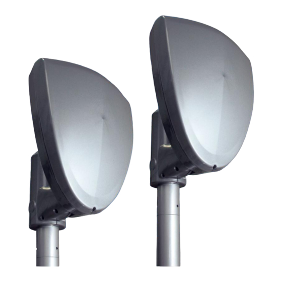
- Page 1 CORAL Barriera a Microonde per protezioni esterne Manuale di Installazione External Microwave Protection Barrier Installation Handbook Edizione / Edition 1.5...
-
Page 2: Table Of Contents
CIAS Elettronica S.r.l. Ed. 1.5 INDICE 1. DESCRIZIONE ..................................3 1.1 D ..................................3 ESCRIZIONE 2 INSTALLAZIONE ................................... 4 2.1 M ..............................4 ONTAGGIO DELLE UNITÀ 2.2 N ................................4 UMERO DI RATTE 2.3 C ..............................5 ONDIZIONI DEL ERRENO 2.4 P... - Page 3 CIAS Elettronica S.r.l. Ed. 1.5 INDEX 1. DESCRIPTION ..................................27 1.1 D ..................................27 ESCRIPTION 2. INSTALLATION .................................. 28 2.1 B ................................28 ARRIER ASSEMBLY 2.2 N ..............................29 UMBER OF ECTIONS 2.3 G ............................... 30 ROUND CONDITIONS 2.4 P ..............................
-
Page 4: Descrizione
1. DESCRIZIONE 1.1 Descrizione CORAL è una barriera a microonde per protezioni volumetriche perimetrali esterne. CORAL è in grado di rilevare la presenza di un corpo che si muove all‟interno di un campo sensibile instauratosi tra il Trasmettitore (TX) e il Ricevitore (RX). -
Page 5: Installazione
2 INSTALLAZIONE 2.1 Montaggio delle unità Fissare le unità ricevente (Rx) e trasmittente (Tx) al palo “CORAL-SP” (opzionale) o ad un palo che abbia le caratteristiche riportate nella figura seguente: F O R O P E R U S C ITA... -
Page 6: Condizioni Del Terreno
CIAS Elettronica S.r.l. Ed. 1.5 E R R AT O E R R AT O Fig.1a Fig.1d C O R R E T T O C O R R E T T O Fig.1b Fig.1e Fig.1c C O R R E T T O C O R R E T T O Fig.1f... -
Page 7: Ampiezza Dei Fasci Sensibili
L u n g h e zza d ella tra tta [m ] 1 0 0 Figura 3 Larghezza della zona sensibile a metà tratta per CORAL 100 sul piano orizzontale (campo libero) Manuale di Installazione Pagina 6 di 52... -
Page 8: Lunghezza Delle Zone Morte In Prossimità Degli Apparati
L u n g h e zza d ella tra tta [m ] 1 0 0 Figura 3a Altezza della zona sensibile a metà tratta per CORAL 100 sul piano verticale (campo libero) D ia m e tro zo n a S e n s ib ilità... - Page 9 L u n g h e zza zo n a m o rta [m ] Figura 5 Lunghezza della zona morta in prossimità degli apparati in funzione dell’altezza dal centro dell’antenna al suolo per CORAL 100 1 0 0 1 0 0 A ltez za d a l s u o lo S e n s ib ilità...
-
Page 10: Collegamenti
CIAS Elettronica S.r.l. Ed. 1.5 3. COLLEGAMENTI 3.1 Morsettiere, connettori e Funzionalità dei Circuiti 3.1.1 Circuito Trasmettitore M S 1 1 3 ,8 V G N D JP3 MOD M P R 50% - 10% S W 3 J P 2 L E D... - Page 11 CIAS Elettronica S.r.l. Ed. 1.5 CONNETTORE J2 TRASMETTITORE Simbolo Funzione Massa per Oscillatore a MW Collegamento per Oscillatore a MW Massa per Oscillatore a MW CONNETTORE J3 TRASMETTITORE Simbolo Funzione 1-2-3-5-8-9-10-11- N.C. Non Connesso 14-15 Massa +13,8 Tensione di Alimentazione (13,8 V )
-
Page 12: Circuito Ricevitore
G U A ST O L E D TA M P E R Figura 9 Disposizione topografica dei componenti nel circuito Rx Nelle seguenti tabelle sono indicate le funzioni delle morsettiere presenti sulla scheda CORAL MORSETTIERA MS1 RICEVITORE Mors Simbolo... - Page 13 CIAS Elettronica S.r.l. Ed. 1.5 CONNETTORE J1 RICEVITORE Simbolo Funzione Massa per Rivelatore a Microonde Collegamento per Rivelatore a Microonde (Detector) Massa per Rivelatore a Microonde CONNETTORE J3 RICEVITORE Simbolo Funzione 1-2-3-5-8-10-11-13- N.C. Non Connesso 15-16 Massa +13,8 Tensione di Alimentazione (13,8 V )
- Page 14 CIAS Elettronica S.r.l. Ed. 1.5 SELETTORE DI FUNZIONI SUL RICEVITORE Simbolo Funzione Posizione 1 = Allineamento Barriera Posizione 2 = Acquisizione Canale, Valore di Campo e Indicazione della Qualità dell‟Allineamento Posizione 3 = Walk Test e verifica della Qualità dell‟Allineamento Posizione 4 = Normale operatività...
-
Page 15: Circuito Alimentatore E Carica Batteria
CIAS Elettronica S.r.l. Ed. 1.5 3.3.3 Circuito Alimentatore e Carica Batteria C n 1 M P R G N D 1 3 ,8 V M S 3 M P R G N D M S 1 M S 2... - Page 16 CIAS Elettronica S.r.l. Ed. 1.5 CONNETTORE CN1 ALIMENTATORE Mors Simbolo Funzione 13,8V Positivo per alimentazione circuito (+13,8V ) Negativo per alimentazione circuito Positivo per presenza rete (+14,6V ) LED DELL’ALIMENTATORE Simbolo Funzione Default Indicazione Presenza Rete FUSIBILE DELL’ALIMENTATORE Simbolo...
-
Page 17: Collegamento All'alimentazione Principale
È possibile utilizzare il trasformatore di sicurezza Toroidale mod. TRTOR montato all‟interno delle teste Tx e Rx di CORAL. In ogni caso occorre attenersi scrupolosamente alle prescrizioni contenute nelle leggi e normative vigenti in materia di installazioni fisse di apparati collegati permanentemente alla rete di alimentazione come la Legge 46/90 e la Normativa CEI 64-8. -
Page 18: Collegamento Alla Centrale
CIAS Elettronica S.r.l. Ed. 1.5 3.3 Collegamento alla Centrale Le connessioni alla Centrale di elaborazione devono essere effettuate mediante cavi schermati. 3.3.1 Contatti di allarme: Allarme, Manomissione, Guasto Le uscite degli apparati sono costituite: sul ricevitore da 3 contatti normalmente chiusi liberi da potenziale, per la segnalazione dei seguenti stati: ... -
Page 19: Connessioni Per Sincronismo
CIAS Elettronica S.r.l. Ed. 1.5 3.3.2 Connessioni per Sincronismo Per effettuare il Sincronismo tra due Trasmettitori occorre connettere tra loro i morsetti 8 “SYNC” ed i morsetti 7 “GND” della morsettiera MS2 dei due Trasmettitori. È Inoltre necessario selezionare un Trasmettitore come “Master” e l‟altro come “Slave”... -
Page 20: Allineamento E Verifica
4. ALLINEAMENTO E VERIFICA 4.1 Allineamento e Verifica Le barriere CORAL sono dotate di un sistema di allineamento elettronico, di un sistema di regolazione dei parametri di lavoro e di un sistema di test, che rendono particolarmente semplici ed efficaci sia le operazioni di installazione che di manutenzione periodica, senza la necessità... -
Page 21: Operazioni Sul Ricevitore
CIAS Elettronica S.r.l. Ed. 1.5 5. Poiché l‟allineamento verticale richiede di operare sullo snodo passacavo interno alla testa, attendere, prima di richiudere la testa, il termine delle operazioni di allineamento. 6. Alla fine delle operazioni, richiudere la testa a MW, accostando il radome al fondo ,quindi avvitare le 6 viti. - Page 22 (per esempio passando una mano davanti all‟antenna del trasmettitore), in questo modo una sola persona potrà facilmente ed efficacemente effettuare l‟allineamento delle barriere CORAL. g. Ottenuto il miglior allineamento (quindi il massimo segnale disponibile) bloccare il movimento orizzontale sia sul Ricevitore sia sul Trasmettitore.
- Page 23 è possibile regolare la sensibilità della barriera CORAL, agendo sul commutatore SW5. La regolazione di default è “7” e rappresenta la regolazione ottimale nella maggior parte dei casi. Volendo aumentare la sensibilità, occorre regolare questo commutatore a valori maggiori, cioè: “8”, “9”, “A”,...
- Page 24 Alto Incremento di Sensibilità per Piccoli Bersagli 6. Portando il commutatore di funzione SW1 in posizione 4, si ripristina la normale operatività della barriera CORAL. La normale operatività, è ripristinata anche quando si chiude il radome, qualunque sia la posizione del commutatore SW1.
-
Page 25: Manutenzione E Assistenza
CIAS Elettronica S.r.l. Ed. 1.5 5. MANUTENZIONE E ASSISTENZA 5.1 Ricerca Guasti In caso di falsi allarmi, verificare i parametri riscontrati durante l’Installazione che saranno stati registrati nell‟apposita Scheda di Collaudo allegata e se si riscontrano delle variazioni che eccedono i limiti indicati, rivedere i relativi punti nel capitolo “... -
Page 26: Caratteristiche
CIAS Elettronica S.r.l. Ed. 1.5 . CARATTERISTICHE 6.1 Caratteristiche Tecniche CARATTERISTICHE TECNICHE Note Frequenza di lavoro F1 10.58 GHz Frequenza di lavoro F2 9.9 GHz Frequenza di lavoro F3 9.46 GHz Frequenza di lavoro F4 10.525 GHz Potenza 20mW 500 mW e.i.r.p... -
Page 27: Caratteristiche Funzionali
CIAS Elettronica S.r.l. Ed. 1.5 6.2 Caratteristiche Funzionali Analisi della Frequenza del Canale di Modulazione impiegato (16 canali) Analisi del Valore Assoluto del Segnale ricevuto per garantire un buon rapporto segnale/rumore. (Segnale Basso) Analisi del Valore Assoluto del Segnale ricevuto per segnalare guasti, deterioramenti, mascheramenti. - Page 28 1.1 Description CORAL is a microwave barrier specifically designed to external volumetric protection. CORAL detects something which is moving between the Transmitter (TX) and the Receiver (RX). CORAL analyze the received signal and processed in order to obtain the maximum performance, therefore less false alarms rate and more security.
- Page 29 Ed. 1.5 2. INSTALLATION 2.1 Barrier assembly To install the CORAL barrier fix the Tx head on one pole, and the Rx head on another pole. Is available (Optional) the “CORAL-SP” which is specifically designed to be used to install CORAL.
- Page 30 CIAS Elettronica S.r.l. Ed. 1.5 2.2 Number of Sections Before the installation, we have to think about how to install the system. Therefore, remember that it‟s always preferable to install a even number of section. This because in a close perimeter which is made of an odd number of sections it‟s present one corner where there are one Transmitter and one Receiver which can produce an interference between themselves.
- Page 31 CIAS Elettronica S.r.l. Ed. 1.5 2.3 Ground conditions It‟s advise against to install the equipment along sections where are present high grass (more than 10 cm), ponds, longitudinal stream, and all those types of grounds which its conformation is rapidly changeable. Use “20cm Special Antenna” for installation on concrete, asphalt and all those reflective pavements with distance longer than 50m.
- Page 32 (”0 ”) R a n g e [m ] 1 0 0 Figure 3 Horizontal plane Half range sensitive zone dimension for CORAL 100 (free space) H a lf ra n g e M ax im u m s e n s itivity (”F ”)
- Page 33 The suggested height, for standard installations, should be about 80 cm. (85/90cm for 100m barriers), from the ground and the centre of the equipment. With medium sensitivity setting, the suggested crossing overlap is at least 5 m., for CORAL-220 model and at least 3,5 m. for CORAL100 model.
- Page 34 [c m ] D e a d Z o n e le n g h t [m ] Figure 6 CORAL 220: Dead zone length near the equipment versus antenna centre height from ground. Installation Handbook...
- Page 35 S Y N C J p 1 M S 2 Figure 8 Layout of connectors, jumpers, LEDs and presetting in transmitter board The following tables show the connector pin functions present on the CORAL Transmitter PCB TRANSMITTER TERMINAL BLOCK MS1 Term Symbol Function...
- Page 36 CIAS Elettronica S.r.l. Ed. 1.5 TRANSMITTER CONNECTOR J2 Symbol Function Ground to MW oscillator Connection for MW oscillator Ground to MW oscillator TRANSMITTER CONNECTOR J3 Symbol Function N.C. Not connected 1-2-3-5-8-9-10-11- 14-15 Ground +13,8 V Supply Voltage (13,8 V )
- Page 37 FA U LT L E D L E D Figure 9 Layout of connectors, jumpers, LED and presetting in receiver board The following tables shows the connector pin functions present on CORAL Receiver board. RECEIVER TERMINAL BLOCK Tem Symbol Function 13,8V...
- Page 38 CIAS Elettronica S.r.l. Ed. 1.5 RECEIVER CONNECTOR J2 Symbol Function Ground to MW detector Connection for MW Detector Ground to MW detector RECEIVER CONNECTOR J3 Symbol Function N.C. Not connected 1-2-3-5-8-10-11-13- 15-16 Ground +13,8 V Supply Voltage (13,8 V )
- Page 39 CIAS Elettronica S.r.l. Ed. 1.5 RECEIVER FUNCTION SELECTION SWITCH Symbol Function Position 1 = Barrier Alignment Position 2 = Acquisition of: Channel Number, Value of Received Field and indication of Alignment Quality Position 3 = Walk-Test and indication of alignment quality...
- Page 40 CIAS Elettronica S.r.l. Ed. 1.5 3.3.3 Power supply and Battery charger circuit C n 1 M P R G N D 1 3 ,8 V M S 3 M P R G N D M S 1 M S 2...
- Page 41 CIAS Elettronica S.r.l. Ed. 1.5 POWER SUPPLY CONNECTOR CN1 Term Symbol Function 13,8V Positive Supply Voltage (+13,8V ) Negative Supply Voltage (0V ) Main Presence Voltage (+14,6V = main and Power Supply POWER SUPPLY LED Symbol Function Default Main presence indication...
- Page 42 CIAS Elettronica S.r.l. Ed. 1.5 3.2 Equipment Connection to the Power Supply Even when the equipment is DC powered ( 13,8 V ), it still operates properly, but it is advisable to power it by Alternating Current ( 19 or 24 V~ ) or (24 V ) using the power supply and battery charger included.
- Page 43 CIAS Elettronica S.r.l. Ed. 1.5 3.3 Connection to the Control Panel Electrically shielded cables must be used to make the connections to the Control Panel. 3.3.1 Alarm contacts: Alarm, Tamper, Fault On receiver PCB are present 3 static relays with dry contacts normally closed. By means of these contacts it‟s possible to communicate to the control panel the following conditions:...
- Page 44 CIAS Elettronica S.r.l. Ed. 1.5 3.3.2 Synchronism connection For the Synchronism operation between two Transmitters, it is necessary to interconnect the terminals 8 “SYNC” and 7 “GND” of terminal block MS2 of both Transmitters. It is also necessary to select one Transmitter as “Master” and the other as “Slave”, by means of jumper Jp1.
- Page 45 4.1 Adjustment and Testing A built in electronic alignment, parameter set and test tool, is provided in the receiver head of the CORAL barriers. This is a very useful system both for installation and periodical maintenance without any other instrument.
- Page 46 CIAS Elettronica S.r.l. Ed. 1.5 5. Since to execute the vertical alignment is necessary to operate on the junction inside the head, is advisable to wait until the end of the alignment operation to close the head. 6. Finally close the MW head using the 6 screws to fix the radome.
- Page 47 CIAS Elettronica S.r.l. Ed. 1.5 e. If during the orientation operation the sound„s frequency increase, it means that the received signal is higher than the previous. If the signal is much more the sound can be continuous. Press again the button S1, the sound will has a lower intermittent frequency.
- Page 48 CIAS Elettronica S.r.l. Ed. 1.5 5. Turn the functions‟ switch SW1 in the position 3, it enables the Wak-Test function. In this condition the barrier generate sounds related to the variation in the microwave beam. During this operation you can change the parameters ( sensitivity SW5 and type of answer SW6).
- Page 49 CIAS Elettronica S.r.l. Ed. 1.5 ADJUSTAMENT OF TYPE OF ANSWER Type of Answer Setting Very High Decrease of Sensitivity Use this for targets very big or very close to the heads Tx and Rx. (Big birds, cats that can jump close to the heads ect.)
- Page 50 CIAS Elettronica S.r.l. Ed. 1.5 5. MAINTENANCE AND ASSISTANCE 5.1 Troubleshooting In case of false alarm, check the parameters recorded during the Installation phase (on attached Test Sheet), if there are divergences with permitted limits check again the related points in chapter "Adjustment and Testing (4)"...
- Page 51 CIAS Elettronica S.r.l. Ed. 1.5 6. CHARACTERISTICS 6.1 Technical characteristics TECHNICAL CARACTERISTICS Note Working Frequency F1 10.58 GHz Working Frequency F2 9.9 GHz Working Frequency F3 9.46 GHz Working Frequency F4 10.525 GHz Maximum power 20mW 500 mW e.i.r.p.
- Page 52 CIAS Elettronica S.r.l. Ed. 1.5 6.2 Functional Characteristics Analysis Modulation channel frequency processing (16 channels) Analysis Absolute received signal value processing, To guarantee the S/N optimal value (Low level signal). Analysis Absolute received signal value processing, for fault detection, behaviour deterioration, masking.
- Page 53 SCHEDA DI COLLAUDO – TEST SHEET CORAL TX NUMERO DI SERIE SERIAL NUMBER: Cliente/Customer Indirizzo/Address Barriera /Barrier N° VALORI MISURATI SUL TRASMETTITORE – MEASURED VALUES ON THE TRASMITTER VALORI MISURATI VALORI TIPICI MISURE MEASURED VALUES STANDARD MEASUREMENTS INSTALLAZIONE MANUTENZIONE VALUES...
- Page 54 SCHEDA DI COLLAUDO – TEST SHEET CORAL RX NUMERO DI SERIE SERIAL NUMBER: Cliente/Customer Indirizzo/Address Barriera /Barrier N° VALORI MISURATI SUL RICEVITORE – MEASURED VALUES ON THE RECEIVER VALORI MISURATI VALORI TIPICI MISURE MEASURED VALUES MEASUREMENTS INSTALLAZIONE MANUTENZIONE STANDARD INSTALLATION...
- Page 55 NOTE:...
- Page 56 Con la presente, CIAS Elettronica, dichiara che questo rivelatore di intrusione “CORAL ” è conforme ai requisiti essenziali ed alle altre disposizioni rilevanti della Direttiva 1999/5/CE (Art.3.1 -3.1 -3.2) Hereby, CIAS Elettronica, declares that this movement detector “CORAL” is in compliance with the essential requirement and other relevant provisions of Directive 1999/5/EC (Art.3.1...
Need help?
Do you have a question about the CORAL and is the answer not in the manual?
Questions and answers