Table of Contents
Advertisement
Available languages
Available languages
Quick Links
GSM control for Lockdown Alert System
Installation and user manual
Notice d'installation et d'utilisation
www.bodet-time.com
Ensure upon reception that the product has not been damaged during delivery.
S'assurer à réception que le produit n'a pas été endommagé durant le transport pour réserve au transporteur.
GSM CONTROL
COMMANDE GSM
Commande GSM pour alertes PPMS
BODET Time & Sport
1 rue du Général de Gaulle
49340 TREMENTINES - France
Tel support France: 02 41 71 72 99
Tel export: +33 2 41 71 72 33
Advertisement
Table of Contents

Summary of Contents for Bodet GSM CONTROL
- Page 1 GSM CONTROL COMMANDE GSM GSM control for Lockdown Alert System Commande GSM pour alertes PPMS Installation and user manual Notice d’installation et d’utilisation BODET Time & Sport 1 rue du Général de Gaulle 49340 TREMENTINES - France Tel support France: 02 41 71 72 99 www.bodet-time.com...
-
Page 2: Table Of Contents
1.4.2. Safety - Electrical installation 1.4.3. Safety - Mechanical installation 1.4.4. Safety - Opening the product 1.5 Presentation of the product 1.5.1. Description of the GSM control 1.5.1.1 Using the “Stop / Reset” button 1.5.1.2 Behaviour of the LEDs 1.5.2. General operation 2. - Page 3 3.3.4. Setting the OUT relays 3.3.5. Setting the IN alarm inputs 3.3.6. Activation and setting of the alarm 3.3.7. Adding contacts 3.3.8. Checking the contact list 3.3.9. Configuration and security check 3.3.10. Other useful commands 3.3.10.1 Activation / deactivation of the “BLOCK” mode 3.3.10.2 Using the NEWS function 3.3.10.3 Viewing the contact list and details of a contact 3.3.10.4 Changing the name of a contact...
- Page 4 Table des matières 1. VÉRIFICATION INITIALE ET GÉNÉRALITÉS 1.1 Introduction 1.2 Principe de fonctionnement 1.3 Déballage du produit 1.4 Consignes de sécurité - précautions d’utilisation 1.4.1. Utilisation de la notice 1.4.2. Sécurité - Installation électrique 1.4.3. Sécurité - Installation mécanique 1.4.4.
- Page 5 3.3.4. Paramétrage des relais OUT 3.3.5. Paramétrage des entrées alarme IN 3.3.6. Activation et paramétrage de l’alarme 3.3.7. Ajouts des contacts 3.3.8. Vérification du répertoire 3.3.9. Vérification de la configuration et sécurité 3.3.10. Autres commandes utiles 3.3.10.1 Activation / désactivation du mode «BLOCK» 3.3.10.2 Utilisation de la fonction NEWS 3.3.10.3 Visualisation du répertoire et détails d’un contact 3.3.10.4 Modification du nom d’un contact...
- Page 6 SAFETY INFORMATION The following pictograms are used to illustrate risks or sources of danger when installing, using and maintaining this product. Symbol Description IEC60417 - 1641 Operating instructions IEC60417 - 5031 Direct current IEC60417 - 5032 Alternating current IEC60417 - 6042 Caution, risk of electric shock IEC60417 - 0434b Caution...
-
Page 7: Initial Check And General Information
- Receive a warning SMS in case of triggering for 2 types of alarms, including, for example, lockdown intrusion: in case of an alarm on an input of the GSM control box (activated by a relay output of the Sigma master clock or another system), an SMS will be sent to the programmed telephone numbers. -
Page 8: Safety Instructions - Precautions For Use
In order to ensure optimal operation of the GSM control box, choose an installation location for the GSM reception antenna that offers good reception without major obstacles to the outside (reinforced concrete walls, metal screens, metal shelves, etc.). -
Page 9: Presentation Of The Product
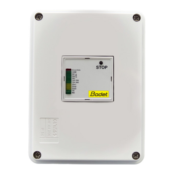
1.5 Presentation of the product 1.5.1. Description of the GSM control Reserved area L N N for the passage IN 1 IN 2 IN 3 of the power cables RS485 STOP Error OUT1 OUT2 OUT3 IN 5 IN 4 OUT1 OUT2 OUT3... -
Page 10: Using The "Stop / Reset" Button
The INCALL(1/2/3) functions linked to the OUT(1/2/3) relay outputs respectively allow the remote triggering of an alert or event by an incoming call. To do this, the call must be made to the SIM card number in the GSM control from a registered number with the appropriate rights to the product. -
Page 11: Installation
- a commercially available mobile phone with a SIM card, - an additional SIM card to be installed in the GSM control box. We recommend a SIM card with a minimum contract that includes unlimited SMS and the ability to receive phone calls. -
Page 12: Electrical Installation
2.4 Electrical installation OUT 1 brown blue green brown yellow white yellow / green 2-pair cable supplied and wired white yellow brown green brown yellow yellow External C1 OV white Input A brown white pink OUT 3 OUT 2 green grey green pink... -
Page 13: Configuration
- Spaces between words are mandatory and are represented as follows: = space, - After each instruction sent by SMS, the GSM control box sends an SMS response to the mobile phone to confirm the programming, - It is imperative to attach the chosen PIN code (by default: #1513) at the end of each programming SMS, otherwise the instruction is rejected. -
Page 14: Setting Via Sms
3.3 Setting via SMS In order to configure the GSM control box, the following parts of the manual must be followed. 3.3.1. Verification Before you start programming the product, check that the product responds to your SMS messages with the following... -
Page 15: Setting The Out Relays
3.3.4. Setting the OUT relays Steps Command to be sent by SMS Description Setting the name of output OUT1 (max 10 characters). NAMEOUT1 NEWNAME #PINcode Example: newname = Intrusion Configuration of relay OUT1. INCALL1 #PINcode Setting the name of output OUT2 (max 10 characters). -
Page 16: Checking The Contact List
Important: Do not lose the new SIM card PIN code. A return to factory settings does not change the SIM card PIN code. After a return to factory settings, the default PIN code expected by the GSM control box is: 1513. -
Page 17: Other Useful Commands
3.3.10.2 Using the NEWS function Step Command to be sent by SMS Description Sending a message to the GSM control. Message: 140 characters max. The sender receives the message back to confirm that it has been taken into account. NEWSLETTER:... -
Page 18: Changing A Contact's Phone Number
3.3.10.5 Changing a contact’s phone number Steps Command to be sent by SMS Description Contact identification (name, location(s) and TEST TELNUMBER +33xxxxxxxxx #PINcode assignment(s)) from its telephone number. Changing the phone number of a contact from its location number (XX). TELNR +33xxxxxxxxx This step must be done twice if a number is stored... -
Page 19: Examples Of Use
4. EXAMPLES OF USE In order to illustrate how the GSM control works for triggering an event in a school, here are some examples of use. For the rest of the examples, we consider: - The school is called “Victor Hugo”,... -
Page 20: Technical Characteristics
5. TECHNICAL CHARACTERISTICS Characteristics Values Operating voltage..........230V 50/60 Hz Power consumption..........max. 30 mA Input power............3W on average External fuse recommended....... 2A, 250V 250 V , 16 A (resistive load) Switching power..........250 V , 3A (inductive load) (external fuse required) 24 V , 16 A... -
Page 21: Appendices
6. APPENDICES As an example, here is the list of responses received by SMS for the configuration and verification stages sent by SMS (for simplicity, we will deliberately limit ourselves to a single contact / a single group to illustrate the commands sent by SMS in steps 28/29/30). - Page 22 BodetGSM 0.48 Client product name - Firmware version G3_ALARMSMS: OFF Function disabled G3_INCALL1: NO Function disabled G3_INCALL2: NO Function disabled RESET #PINcode G3_INCALL3: NO Function disabled G3_NEWS: OFF Function disabled G3_SMSFORWARD: NO Function disabled BodetGSM 0.48 Client product name - Firmware version G3_ALARMSMS: ON Function enabled G3_INCALL1: NO...
- Page 23 BodetGSM 0.48 Client product name - Firmware version IN1: No Name Not used IN2: No Name Not used IN3: No Name Not used NAMEOUT2 ALERT #PINcode IN4: No Name Alarm input used - unnamed IN5: No Name Alarm input used - unnamed OUT1: ALERT A Relay output used - named OUT2: ALERT B...
- Page 24 Bodet GSM 0.48 Client product name - Firmware version Alarm: ON Alarm status (ON/OFF) GSM: 50% Level of GSM reception Temp: 19.3C Temperature of the device 230V List of 230V inputs (IN1/2/3) IN1: LO Not used IN2: LO Not used...
- Page 25 INFORMATIONS RELATIVES À LA SÉCURITÉ Les pictogrammes ci-dessous permettent d’illustrer des risques ou des sources de danger lors de l’installation, de l’utilisation et de la maintenance de ce produit. Symbole Description IEC60417 - 1641 Manuel d’utilisation IEC60417 - 5031 Courant continu IEC60417 - 5032 Courant alternatif IEC60417 - 6042...
-
Page 26: Vérification Initiale Et Généralités
1. VÉRIFICATION INITIALE ET GÉNÉRALITÉS Nous vous remercions d’avoir choisi le boîtier de commande GSM pour alerte PPMS BODET. Ce produit a été conçu avec soin pour votre satisfaction selon les règles du système qualité ISO9001 et ISO14001. Nous vous recommandons de lire attentivement ce manuel avant l’installation du produit. -
Page 27: Consignes De Sécurité - Précautions D'utilisation
1.4.4. Sécurité - Ouverture du produit L’intérieur de cet équipement ne possède pas de pièces réparables par l’utilisateur : contacter l’assistance clientèle BODET si cet équipement doit être réparé. L’ouverture du produit pour son installation ou pour une opération de maintenance est autorisée, uniquement par une personne qualifiée :... -
Page 28: Présentation Du Produit
1.5 Présentation du produit 1.5.1. Descriptif de la commande GSM Zone réservée L N N au passage des IN 1 IN 2 IN 3 câbles secteur RS485 STOP Error OUT1 OUT2 OUT3 IN 5 IN 4 OUT1 OUT2 OUT3 Description Etats / Commentaires A: passage câble GSM + câble 2 paires B: passage câble 3 paires... -
Page 29: Utilisation Du Bouton "Stop / Reset
1.5.1.1 Utilisation du bouton «Stop / Reset» Ce bouton permet d’effectuer plusieurs actions sur le produit en corrélation avec la LED Error/Info. Action Manipulation utilisateur requise État(s) de la LED Error / Info Blocage du déclenchement Appuyer pendant 2 secondes sur le bouton. Éteinte >... -
Page 30: Installation
2. INSTALLATION 2.1 Pré-requis Pour l’utilisation et la configuration du boîtier de commande GSM, les éléments suivants sont requis : - un téléphone portable disponible dans le commerce avec une carte SIM, - une carte SIM supplémentaire à installer dans le boîtier de commande GSM. Nous recommandons une carte SIM avec contrat minimum comprenant les SMS en illimités ainsi que la possibilité... -
Page 31: Installation Électrique
2.4 Installation électrique OUT 1 marron bleu vert marron jaune blanc jaune / vert Câble 2 paires fourni et câblé blanc jaune marron vert marron jaune jaune External C1 OV blanc Input A marron blanc rose OUT 3 OUT 2 vert gris vert... -
Page 32: Configuration
3. CONFIGURATION 3.1 Règles générales pour la configuration par SMS La configuration s’effectue depuis des instructions envoyées au boîtier de commande GSM (vers le numéro de la carte SIM se trouvant à l’intérieur) par SMS à partir d’un téléphone portable. Cette communication par SMS permet de configurer l’intégralité... -
Page 33: Paramétrage Par Sms
3.3 Paramétrage par SMS Afin de configurer le boîtier de commande GSM, suivez obligatoirement les parties suivantes de la notice. 3.3.1. Vérification Avant de démarrer la programmation du produit, vérifiez que le produit réagit à vos SMS avec la commande suivante : Etapes Commande à... -
Page 34: Paramétrage Des Relais Out
3.3.4. Paramétrage des relais OUT Etapes Commande à envoyer par SMS Description Paramétrage du nom de la sortie OUT1 (max 10 caractères). NAMEOUT1 NEWNAME #CodePIN Exemple: newname = Intrusion Configuration du relais OUT1. INCALL1 #CodePIN Paramétrage du nom de la sortie OUT2 (max 10 caractères). -
Page 35: Vérification Du Répertoire
3.3.8. Vérification du répertoire Etapes Commande à envoyer par SMS Description Identification des contacts enregistrés Vérifiez que les (nom et emplacement) dans chaque groupes G1, groupe. (X= 1,2,3,4,5) TEST #CodePIN G2, G3 et G4 Remplacer GX successivement par G1, contiennent des G2, G3, G4 et G5. -
Page 36: Autres Commandes Utiles
3.3.10. Autres commandes utiles 3.3.10.1 Activation / désactivation du mode «BLOCK» Etapes Commande à envoyer par SMS Description Indication de l’état du produit à l’instant courant STATUS #CodePIN pour vérifier la configuration. Activation du mode «BLOCK». Attention, l’activation de cette fonction BLOCK #CodePIN empêche le déclenchement des alertes. -
Page 37: Modification Du Numéro De Téléphone D'un Contact
3.3.10.5 Modification du numéro de téléphone d’un contact Etapes Commande à envoyer par SMS Description Identification du contact (nom, emplacement(s) et TEST TELNUMBER +33xxxxxxxxx #CodePIN affectation(s)) à partir de son numéro de téléphone. Modification du numéro de téléphone d’un contact à partir de son numéro d’emplacement (XX). -
Page 38: Exemples D'utilisation
4. EXEMPLES D’UTILISATION Afin d’illustrer le fonctionnement de la commande GSM pour le déclenchement d’un évènement dans une école, voici ci-dessous des exemples d’utilisation. Pour la suite des exemples, on considère : - L’école s’appelle «Victor Hugo», - 7 numéros sont enregistrés dans la commande GSM avec les attributions suivantes dans les groupes : Contact Numéro de téléphone Affectation Groupe(s) -
Page 39: Caractéristiques Techniques
5. CARACTÉRISTIQUES TECHNIQUES Caractéristiques Valeurs Tension de fonctionnement......... 230V 50/60 Hz Consommation électrique........max. 30 mA Puissance absorbée..........3W en moyenne Fusible externe recommandé......2A, 250V 250 V , 16 A (charge ohmique) Puissance de commutation......... 250 V , 3A (charge inductive) (fusible externe requis) 24 V , 16 A... -
Page 40: Annexes
6. ANNEXES Pour exemple, voici la liste des réponses reçues par SMS pour les étapes de configuration et de vérification envoyées par SMS (à des fins de simplification, on se limitera volontairement à un seul contact / un seul groupe pour illustrer les commandes envoyées par SMS sur les étapes 28/29/30). - Page 41 BodetGSM 0.48 Nom de l’appareil - Version du firmware G3_ALARMSMS: OFF Fonction désactivée G3_INCALL1: NO Fonction désactivée G3_INCALL2: NO Fonction désactivée RESET #CodePIN G3_INCALL3: NO Fonction désactivée G3_NEWS: OFF Fonction désactivée G3_SMSFORWARD: NO Fonction désactivée BodetGSM 0.48 Nom de l’appareil - Version du firmware G3_ALARMSMS: ON Fonction activée G3_INCALL1: NO...
- Page 42 BodetGSM 0.48 Nom de l’appareil - Version du firmware IN1: No Name Non utilisé IN2: No Name Non utilisé IN3: No Name Non utilisé NAMEOUT2 ALERTE #CodePIN IN4: No Name Entrée alarme utilisée - non nommée IN5: No Name Entrée alarme utilisée - non nommée OUT1: ALERTE A Sortie relais utilisée - nommée OUT2: ALERTE B...
- Page 43 Bodet GSM 0.48 Nom de l’appareil - Version du firmware Alarm: ON Etat de l’alarme (ON/OFF) GSM: 50% Niveau de réception GSM Temp: 19.3C Température de l’appareil 230V Liste des entrées de commutation 230V (IN1/2/3) IN1: LO Non utilisé IN2: LO Non utilisé...
Need help?
Do you have a question about the GSM CONTROL and is the answer not in the manual?
Questions and answers