Advertisement
Quick Links
Advertisement

Related Manuals for NI Climbing Frames Las Vegas


Summary of Contents for NI Climbing Frames Las Vegas
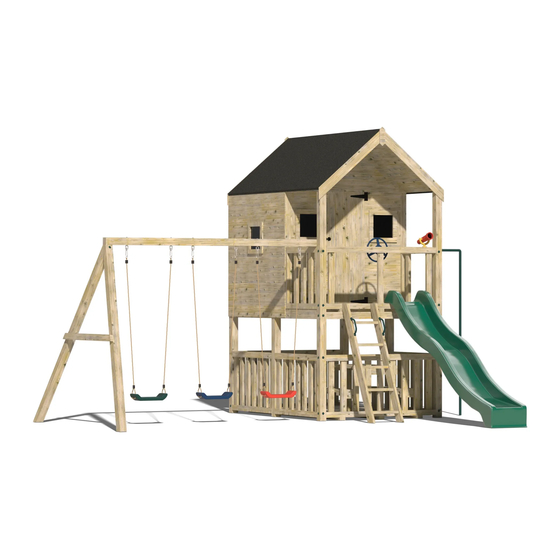
- Page 1 Las Vegas Climbing Frame Instruction Manual...
- Page 2 Parts List Item Description Image Quantity Number Railings 3m post 2 (one cut at 60° with a angle 32mm hole pre- drilled) 3m post for swing bar Holes pre-drilled depending on swing choices 1617mm post...
- Page 3 3300mm post 1735mm post 2420mm post (with a piece of 3” x 1.5” secured to...
- Page 4 1575mm post 2600mm x 1 (in 2 1800mm parts) base (Bottom Base) 1800mm x 3” x 1.5” 2420mm x 3” x 1.5” Decking Approx. screws...
- Page 5 200mm index screws 120mm screws Sides for playhouse Front for playhouse...
- Page 6 Rear for playhouse Set of Steps Roof 2 roof Panels + panels felt for playhouse 3 sheets of felt...
- Page 7 M10 swing 6 (as hook standard, depends on swing choices) 9ft Slide Swing 3 as (varies standard depending customers choice)
- Page 8 Screw covers Fireman’s Pole 2600mm x 1 (in 2 1800mm parts) Top Base...
- Page 9 Bench Top Picnic Table-Top Loose Timber (to secure to railings to support seats and picnic table)
- Page 10 540mm post with 3” x 1.5” secured to 240mm post with 3” x 1.5” secured to 6x60 screws Other components included: Handgrips, telescope, steering wheel, fascia, side trims and bottom trims for playhouse, 20mm roof nails...
- Page 11 Tools needed: • Cordless drill • Handsaw • Spirit Level • Hammer • Shovel • Stepladder • Pencil • Measuring tape • 10mm Hex bit • PZ 2 Drill Bit Ground Preparation • Lay out the base with the six notches, slide and the 3m swing bar in the position that you intend the climbing frames to be placed.
- Page 12 Assembly Instructions All components needed during the assembly are numbered with reference to the parts list, please refer back to the parts list to ensure you are assembling the correct components for each step. Step 1: Platform H-Frame Assembly • Lay two of the 3300mm posts on a level surface with a 1617mm post between them.
- Page 13 Step 2: • Using the 1800mm 3” x 1.5” timber and using the 60mm decking screws screw the timber to the frame (this is to strengthen the H-frame structure, without this additional support at the bottom the frame will twist once it is lifted up)
- Page 14 Step 3: • Repeat the above steps for the second H-frame, only this time use the 1735mm vertical posts.
- Page 15 Step 4: Base assembly (requires heavy lifting, please use at least 3 people) • The first step will be to position and pack your floor so that it is level and is not sagging or bouncing in any places when someone stands on it. This will be made easier if your ground is flat and fairly level.
- Page 16 Step 5: Securing the H-Frames Together • To ensure that the base fits into place use the 2420mm x 3" x 1.5” timber provided to connect the two ‘H’-frames together • The structure should now be able to stand on its own...
- Page 17 Step 6: • Secure the 2420mm posts (with the 3” x 1.5” secured to it) to the H-frames using two 200mm index screws into each 32mm hole. Ensure the 3” x 1.5” timbers are on the top and they should be flush with the top of the 1735mm post...
- Page 18 Step 7: • Secure the final 1617mm post to the middle of the 2420mm posts using two index screws into each of the 32mm holes...
- Page 19 Step 8: Top Base Assembly (requires heavy lifting, please use at least 3 people) • Lift the base and set into its place, with the 3” x 1.5” base supports resting on the three 1617mm posts, the base with no cut outs is for the small H-frame •...
- Page 20 Step 9: Railings Assembly • The railings are now ready to be put into their respective slots, the open ones are for the steps, slide, Rope Bridge and fireman’s pole and the closed ones are for the 8ft rock module, 8ft cargo net and swing module •...
- Page 22 Step 10: Removing H-Frame Supports • Remove the lower H-Frame supports that were added during steps 2 & 5...
- Page 23 Step 11: Making the Opening for the Downstairs Area • Using the 1575mm post, cut it to fit tightly into the middle hole you have dug and the bottom of the 4” x 4” support of the 1 floor. Use decking screws to secure the 1575mm posts to the horizontal 1420mm posts at an angle...
- Page 25 Step 12: Bottom Railings Assembly • The first step is to drill 32mm holes in line with the centre of the top and bottom of the railings for the 120mm screws on the four corner upright posts. Secure the top and bottom of the rails with 120mm screws just like the other railings, and use decking screws to secure the bottom timber of the railings to the decking floor •...
- Page 26 Step 13: Playhouse Assembly • Once the railings are in place you can start to assemble the playhouse. The playhouse comes in 6 pieces, 4 walls and 2 roof panels • Add all 4 walls and screw into place using decking screws. The studs should all line up flush to the outside of the base, except the front which will sit tight to the two side walls...
- Page 28 Step 14: Roof Assembly • Now add the roof panels and screw down using the 40mm chipboard and 65mm decking screws • All that remains is nailing down the felt supplied onto the roof (with the 20mm roof nails supplied)
- Page 29 Step 15: Securing the playhouse to the platform • Once the playhouse is complete, screw decking screws up through the 8ft x 6ft base into the supports of the playhouse base • Also screw decking screws from the inside of the playhouse into the railings to make the railings and playhouse secure...
- Page 30 Step 16: Swing Module Assembly • Lay the 2 x 3m posts (with the ends cut off at 60 degrees) on a flat surface • Place the ends together so that it forms an A-shape • Using the 200mm index screws, screw the ends together, so the two posts meet nice and flush on all sides...
- Page 31 Step 17: • Measure down from the top of the ‘A’ post 900mm to both posts and place a piece of 3” x 1.5” that was used for the lower H-frame supports and secure using decking screws • Cut the 3” x 1.5” timber so that it is flush on both sides of the A-frame...
- Page 32 Step 18: • Place each swing hook through the pre-drilled holes of the 3m post that is square on both ends, secure using the appropriate spanner...
- Page 33 Step 19: • Now the tricky part. The ‘A’-frame is designed to be at an 80° angle (i.e it is not at 90 degrees to the surface). This is best achieved by measuring 11 ft from the end of the climbing frame to the base of the A-frame •...
- Page 34 Step 20: • Once this is achieved (no easy task), then secure both ends into place, screw 120mm screws down into the railing, and 200mm index screws down into each leg of the A-frame...
- Page 35 Step 21: Steps Assembly • The steps might have to be cut or dug into place (depending on the slope of your surface) • They are secured using decking screws through the top and sides of the steps into the base of the tower.
- Page 36 Step 22: Slide Assembly • Using 2 decking screws, secure the slide to the bottom timber of an open railing through the pre-drilled holes in the slide...
- Page 38 Step 23: Fireman’s Pole Assembly • Place the fireman’s pole into its position and mark the position that it will go into the ground, which will be the centre of the railing and out the same distance as the turn in the pole itself •...
- Page 39 Step 24: Picnic Table Assembly • The 540mm 4” x 4” with the 3” x 1.5” screwed to it is for the picnic table leg. This need to be screwed down with decking screws to the underside of the table-top keeping the 3” x 1.5” timber tight to the side of the 3”...
- Page 40 Step 26: • Secure the three pieces of loose timber to the railings in the desired location. Secure them using decking screws and ensure that the timber is at the correct height for the seats and picnic table to rest horizontally on and be secured to...
- Page 41 Step 27: • Place the picnic table on the timber screwed to the railings and ensure that the table-top is horizontal. Once this is done, use decking screws to secure the table-top to the timber secured to the railings...
- Page 42 Step 28: • Use decking screws to secure the 4” x 4” post to the base...
- Page 43 Step 29: • Repeat the previous two steps to secure the picnic table seats to the railings and to the floor Step 30: Swing Attachment • Hang your chosen swings from the swing hooks...
- Page 44 Step 31: Concreting structure • Using postcrete and following the manufacturer’s instructions, concrete all the posts into the ground • The frame should be left overnight before it is used to ensure the postcrete has dried. The final stage is to put on the accessories, press the screw covers into the 32mm holes and give everything a good sand down to avoid the children getting splinters from any rough edges.
- Page 45 Maintaining Your Climbing Frame My climbing frame has been installed, what do I do next? A: If your climbing frame was installed in a grassed area the installers have concreted the frame into the ground. They have left a small exposed hole, where the posts have been sunk into the ground. The reason this has been done is to allow the concrete to set overnight.
Need help?
Do you have a question about the Las Vegas and is the answer not in the manual?
Questions and answers