Advertisement
Quick Links
Advertisement

Related Manuals for NI Climbing Frames Causeway 6ft Climbing Frame


Summary of Contents for NI Climbing Frames Causeway 6ft Climbing Frame
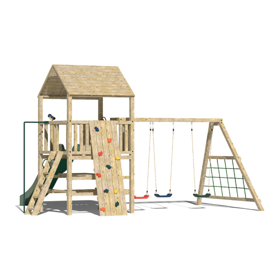
- Page 1 The Causeway (6ft) Climbing Frame Instruction Manual...
- Page 2 Parts List Item Description Image Quantity Number 3m post cut at 40° angle 3m post cut 2 (with at 60° angle 32mm hole pre-drilled) 420mm post 1575mm post...
- Page 3 1755mm x 1170 mm roof panel 6” x 1” small board for roof 6” x 1” large board for roof 1755mm x 1755mm base 1575mm x 3” 2 + 20 for x 1.5” timber picnic table...
- Page 4 1755mm 3” x 5 + 2 for 1.5” timber picnic table Railings 4 (3 open, 1 closed as standard) Open Railing Closed Railing Decking screws...
- Page 5 200mm index screws 120mm screws Set of steps Screw covers...
- Page 6 M10 swing 6 (as hook standard, depends on swing choices) Rock wall 1 (10 rocks standard for 8ft wall) (5ft wall has 5 rock holds) 9ft slide...
- Page 7 Swing (varies 3 as depending standard customers choice) 10ft Monkey 1 (holes Bars pre-drilled for swing hooks) 3m x 3” x 1.5”...
- Page 8 U-Nails 1 bag 16mm Rope 8ft Fireman’s Pole Other components included: Handgrips, telescope, steering wheel.
- Page 9 Tools needed: • Cordless drill • Handsaw • Spirit Level • Hammer • Shovel • Stepladder • Pencil • Measuring tape • 10mm Hex bit • PZ 2 Drill Bit Ground Preparation 1. Lay out the base, slide and the 3m swing bar in the position that you intend the climbing frame to be placed.
- Page 10 Assembly Instructions All components needed during the assembly are numbered with reference to the parts list, please refer back to the parts list to ensure you are assembling the correct components for each step. Step 1: ‘H-Frame’ Assembly • Lay 2 3m posts that are cut at a 40° angle on a level surface •...
- Page 11 Step 3: • Make a mark 2400mm (2.4m) from the top of both 3m posts. If your frame has a picnic or sandpit picnic table, add a second mark to each post 2100mm down from the top of the post •...
- Page 12 Step 4: • Place another 1755mm 3” x 1.5” timber on the 40° angle on the top of the post and screw into place using the 65mm decking screws • Steps 3 and 4 strengthen the H-frame structure, without this additional support at the top and bottom, the frame will twist once it is lifted up Step 5: •...
- Page 13 Step 6: (Requires heavy lifting, please use at least 2 people) • Lift both ‘H’-frames into the holes that have been cut out in the ground • Make sure the ‘H’-frames are orientated correctly (to ensure that the roof will be able to rest on the tops) Step 7: •...
- Page 14 Step 8: Base Assembly • The structure should now be able to stand on its own • Lift the base and place it onto the two horizontal posts. The 3” x 1.5” base supports should sit onto the horizontal posts •...
- Page 15 Step 9: Railings Assembly • There are 4 railings per tower. The open ones are typically for the rope bridge, steps, fireman’s pole, monkey bars and slide; the closed ones are for the rock wall, cargo net and swing module. Ensure to fit the railings in their correct positions depending on the desired layout of the frame.
- Page 16 • For the two sides with 4” x 4” posts with the 3” x 1.5” base supports sitting on them, the decking screws should be screwed in from beneath at an angle between each of the 3” x 1.5” base supports Step 10: •...
- Page 17 Step 11: • Repeat steps 9 and 10 for each railing...
- Page 18 Step 12: Roof Assembly • Place one of the 1755mm x 1170mm roof panels directly onto the ground (so that the shingled part is facing downwards) • Using the ‘v’ boards provided assemble the two roof panels together using decking screws...
- Page 19 Step 13: • Lift the roof onto the climbing frame and ensure it is positioned evenly on all sides before securing the roof to the top of the post using 2 x decking screws for each 2” x 1” support of the roof panel •...
- Page 20 Step 14: Monkey Bar Module Assembly • Lay out the 2 posts on a flat surface • Attach the 420mm post to the top of the posts as shown, using the 200mm screws. Please ensure that the 420mm post is flush with the cut on the top of each 3m post Step 15: •...
- Page 21 Step 16: • Cut the 1755mm timber flush with the A-frame posts Step 17: • Now the tricky part. The ‘A’-frame is designed to be at an 82° angle (i.e it is not at 90 degrees to the ground) • The ‘A’-frame should be then lined up to the centre of the frame •...
- Page 22 Step 18: • Ensure that the monkey bar is flush with the A-frame and is overhanging either side the same distance • Use the 200mm screws provided to screw the monkey bars to the 3m posts of the A-frame, and the 120mm screws to screw down into the 420mm post •...
- Page 23 Step 19: • Place the 3m 3” x 1.5” timber provided at a height of approximately 200mm from the ground to the bottom of the timber • Secure them in place using the decking screws provided Step 20: • Cut the 3” x 1.5” flush with the A-frame posts...
- Page 24 Step 21: Cargo Net Assembly • The height and width of the squares are approximately 300mm apart. Make a mark of these points on the 2 posts and the 3” x 1.5”. Best way to do this is to measure the distance between the 3”...
- Page 25 Step 22: • Place each swing hook through the pre-drilled holes of the 3m monkey bar post, secure using the appropriate spanner Step 23: Steps Assembly • The steps might have to be cut or dug into place (depending on the slope of your surface) •...
- Page 26 Step 24: Fireman’s Pole Assembly • Place the fireman’s pole into its position and mark the position that it will go into the ground, which will be the centre of the railing and out the same distance as the turn in the pole itself •...
- Page 27 Step 25: Rock Wall Assembly • The rock wall is typically made slightly longer than required to allow for a slope • Place the rock wall against the top of a closed railing • Measure the amount you may have to take off the bottom of the rock wall •...
- Page 28 Step 26: Slide Assembly • Using 2 decking screws, secure the slide to the bottom timber of an open railing through the pre-drilled holes in the slide Step 27: Swing Attachment • Hang your chosen swings from the swing hooks...
- Page 29 Step 28: Picnic Table Assembly • Using the existing 1575mm 3” x 1.5” timbers that were placed at the bottom of the climbing frame (Step 7) add an additional 2 x 1575mm 3” x 1.5” timbers beside these to form the seating for the picnic table Step 29: •...
- Page 30 Step 30: • Using 10 x 1575mm x 3” x 1.5” timbers centre these so as to form the table top itself. Screw these into place using the 65mm decking screw provided, again predrilling the holes Step 31: • Cut 3 pieces of 1575mm x 3” x 1.5” to size to use as supports for underneath the benches at each side and for the table and secure these using decking screws...
- Page 31 Step 32: Screw Cover Assembly • Press the screw covers into each of the 32mm holes on the 4 vertical posts that make up the H-Frame and the holes on the A-frame Step 33: Concreting structure • Using postcrete and following the manufacturer’s instructions, concrete all the posts into the ground •...
- Page 32 The final stage is to put on the accessories, give everything a good sand down to avoid the children getting splinters from any rough edges. All screws should also be checked to ensure they are flush to the surface they are securing.
- Page 33 Maintaining Your Climbing Frame My climbing frame has been installed, what do I do next? A: If your climbing frame was installed in a grassed area the installers have concreted the frame into the ground. They have left a small exposed hole, where the posts have been sunk into the ground. The reason this has been done is to allow the concrete to set overnight.
Need help?
Do you have a question about the Causeway 6ft Climbing Frame and is the answer not in the manual?
Questions and answers