Table of Contents
Advertisement
Quick Links
O p p p p e e e e r r r r a a a a t t t t i i i i o o o o n n n n &
O O O
& S S S S e e e e r r r r v v v v i i i i c c c c e e e e
&
&
M a a a a n n n n u u u u a a a a l l l l
M
M
M
DC- 1 80
C C C C o o o o u u u u n n n n t t t t i i i i n n n n g g g g S S S S c c c c a a a a l l l l e e e e
73349
Advertisement
Table of Contents

Subscribe to Our Youtube Channel
Related Manuals for Digi DC-180


Summary of Contents for Digi DC-180
- Page 1 DC- 1 80 C C C C o o o o u u u u n n n n t t t t i i i i n n n n g g g g S S S S c c c c a a a a l l l l e e e e O O O O p p p p e e e e r r r r a a a a t t t t i i i i o o o o n n n n &...
-
Page 3: Table Of Contents
Key Switch Information SPECIFICATIONS Capacities 9-11 INSTALLATION Un-packing Inspection Re-packing 9-11 Un-locking Procedure ELECTRICAL 4.1. DC-180 AC / BATTERY OPERATION DC-180 OPERATIONAL PROCEDURES 13-17 5.1. Tare Reducton 13-14 5,1,1, One Touch Tare 5.1.2. Digital Tare 5.2. Net / Gross 5.3. Unit Weight 5.3.1. -
Page 4: General
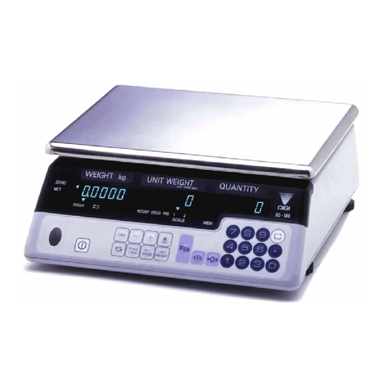
GENERAL 1.1. Description The DC-180 counting scale offers a practical solution to a full range of precision counting applications. There are a variety of models available ranging from a weight capacity of 0.5 lb. through 100 lb. utilizing an internally mounted load cell and a full range of capacities from 0.5 to 50,000 lb. -
Page 5: Keyboard & Display Layout
1.3. Keyboard & Display Panel Layout... -
Page 6: Indicator Lamp Information
1.4. Indicator Lamp Informaton LAMP “ON” Zero When the gross weight is zero. Tare When tare weight is set. Gross When [Gross/Net] key is pressed. Insuff When the net weight is below a specific percentage of capacity weight. Recomp When unit weight recomputing is possible. Memory When quantity is being accumulated or when memory overflows. -
Page 7: Key Switch Information
1.5. Key Switch Information FUNCTIONS On/Off For turning the machine ON and OFF. 0 to 9 Numeric Keys. Decimal Point. Rezero Used to reset the scale to zero. Used to enter the maintenance mode along with other keys Tare Used for setting and clearing tare weight. Kg/Lb Used to change the weighing unit between Kilogram and Pound. -
Page 8: Specifications
This section includes a detailed listing of all pertinent specifications and parameters for the DC-180 counting scales. The system weighing accuracy is 0.02 % . All models meet or exceed the requirements of OIML, Class III, and NIST Handbook, Number 44. -
Page 9: Installation
2. Set-up Procedure 3.1. UNPACKING Each component of the DC-180 system is packed in a specially designed carton. Remove each component from its carton, separate the component from its polystyrene shell assembly and set aside. Inspect the carton interior to be sure that all accessories have been removed from the carton. -
Page 10: Un-Locking Procedure
C) For calibration of the scale, use a thin rod to enable the span switch. Refer to the diagram above for the location of the span switch. Please refer to instructions for Span Adjustment for more detail. Note: For DC-180 with a remote scale, connect the remote scale before plugging the A/C. - Page 11 Do not unplug remote scale from the DC-180 while the DC-180 is powered. 3.4. Unlocking Procedure (Continued) for 1LB. and 2.5LB. Scales The above drawing is for illustration purpose only. Warning! Do Not Turn Scale Upside Down. SET UP PROCEDURES Do the following steps before scale calibration or operation.
-
Page 12: Electrical
4.0. DC-180 AC / BATTERY OPERATION The DC-180 can be operated with AC power or with the optional internal battery. The battery will automatically charge whenever the scale is plugged into AC power. The charging current is regulated by a battery monitor circuit, so that the battery can not be overcharged. -
Page 13: Dc-180 Operational Procedures
5.0. Operation Guide in Weighing Mode 5.1. Tare Reduction : 5.1.1. One Touch Tare Operation : Display in the weighing mode Place 0.5 Lb weight on the platter. (Example : of a .5lb tare) Press the [TARE] key to tare the weight on the platter Remove the weight from the platter Note : The tare operation is valid up to the 4th digit of the weight column. -
Page 14: Unit Weight
5.3. Unit Weight Operation : 5.3.1. Unit Weight Operation by Sampling : 1 Display in the weighing mode 2 Place 10 pcs of the item to be sampled on the platter. 3 Press the [PIECES] key. Please wait for a few seconds for the computation. 4 The Unit Weight Display shows the Unit Weight of the samples (1.255/1000 pieces) and the Quantity Display shows the Quantity of the pieces i.e. -
Page 15: Accumulation
5.4. Accumulation Operation : This following procedure is used if the unit weight is already known. After Unit Weight entry. (See 4.3) Press the [+ + + + ] key. The Total is displayed in the Quantity Display. The memory lamp will glow. After a moment the scale will resume operation mode. Put 1.0lb on the platter Press the [+ + + + ] key. -
Page 16: Clearing Of Accumulated Data
5.6. Clearing of Accumulated Data : From previous operations (See 4.4. & 4.5.) Pressing the [∗ ∗ ∗ ∗ ] key, clears the accumulated total. 5.7. Clearing Unit Weight : Remove weight. Pressing the key, clears the unit weight. 5.8. Scale 1_ _ _ _ 2 Operation : To change between Scale 1 (Built-in) and Scale 2 (Remote), please make sure that bit 1 of Spec 25 in Weight and Measures specification is set to 1. -
Page 17: Recall Item From Memory
5.9. Recall Item From Memory: Version 1.13 and above ID CODE (30 ITEM MEMORY) OPERATION EXAMPLE : Recall Item From Memory: Task Procedure 1. Select Scale And Reset Zero Point Press [SCALE 1 , 2 ] Key And Press [REZERO] Key. 2. -
Page 18: Program Mode
6.0. PROGRAMMING MODE: 6.1. Set Point Programming : 6.1.1. Set Point Programming by % Quantity Set Point 1 : Quantity (See Note Below) , Set Point 2 : % Quantity (See Note Below) Set bit 0 and 1 of Spec 7 to 00 Display in the weighing mode Press the [MODE] key to go into the programming mode. -
Page 19: Set Point Programming By Upper & Lower Limit Quantity
6.1.3. Set Point Programming by Upper and Lower Limit of Quantity Set Point 1 : Quantity (See Note Below), Set Point 2 : Quantity (See Note Below) Set bit 0 and 1 of Spec 7 to 10 Display in the weighing mode Press the [MODE] key to go into the programming mode. -
Page 20: Programming Id Code (30 Item Memory)
6.2. PROGRAMMING ID CODE (30 ITEM MEMORY) Version 1.13 and above PROGRAMMING ID CODE (30 ITEM MEMORY) Task Procedure 1. Enter PROGRAM Mode. Press [MODE] key. 2. Enter ID Code Type ID Code (Up To Four Digits) Example [1] [2] [3] [4], Then Press[CODE] Key. -
Page 21: Maintenance Mode
7.0. MAINTENANCE MODE: 7.1. Scale Calibration Prior to the calibration of the scale, please note that the SPEC settings corresponding to Minimum Display, Weight Decimal Point Position and Load Cell Sensitivity for that particular scale have to be correctly set. Ensure that the[SPAN] Switch is ON. -
Page 22: Spec Setting 1
7.4. Internal Count And A/D Count Display : If the SPEC 25, bit 2 is set, then the [SPAN] Switch must be "ON" to enter this mode. Enter [0] [0] [9] while depressing the [REZERO] Key. Unit Weight Window will display the Internal Count and the Quantity Window will display the A/D Count. -
Page 23: Spec List
7.5. DC-180 Spec. List Rev. 7 Operation Specifications : To enter this mode, enter the numeric keys 1,4,1 while pressing the Rezero Key. Spec No. Bit 3 Bit 2 Bit 1 Bit 0 Power Auto Off Function 0000 : Auto Power Off Disable when Net Wt. = 0 0001 ~ 1111 : Time duration to activate Power Off, equal to the decimal no. - Page 24 To enter this mode, enter the numeric keys 1,4,2 Weight and Measures Specification : while pressing the Rezero Key. The Span Switch must be “ON” to enter this mode. Spec No. Bit 3 Bit 2 Bit 1 Bit 0 Minimum Display ( Scale 1) Minimum Display (Scale 2) 00 : 2 10 : 5...
-
Page 25: Platform Wiring
Spec No. Bit 3 Bit 2 Bit 1 Bit 0 Load Cell Sensitivities Selection (mV/V) (Scale 1) 0000 3.46 4.00 0100 1.95 2.25 1000 1.09 1.27 1100 0.61 0.71 0001 3.00 3.46 0101 1.69 1.95 1001 0.95 1.09 1101 0.53 0.91 0010 2.59... -
Page 26: Shop Notes
7.7. Shop Notes:... - Page 27 DC-180 Limited Warranty Rice Lake Weighing Systems (RLWS) warrants that all RLWS equipment and systems properly installed by a Distributor or Original Equipment Manufacturer (OEM) will operate per written specifications as confirmed by the Distributor/OEM and accepted by RLWS. All systems and components are warranted against defects in materials and workmanship for one year.
Need help?
Do you have a question about the DC-180 and is the answer not in the manual?
Questions and answers