
Related Manuals for Schulze Air press-4 X


Summary of Contents for Schulze Air press-4 X
- Page 1 Instruction manual Version 11.01 Pneumatic press Air press-4 X automatic Version 11.01 1/26...
-
Page 2: Table Of Contents
1. Introduction 1.1 Content 1. Introduction 1.1 Content 1.2 Illustration of the heat press 1.3 Technical data 1.4 Accessory 1.5 Exchangeable heating plates 1.6 Exchangeable base plates 1.7 Safety arrangements of the press 1.8 Safety arrangements at the workspace 2. Initiation 2.1 Tips for transport 2.2 Installation of the heat press 2.3 Connection of the press to compressed air... -
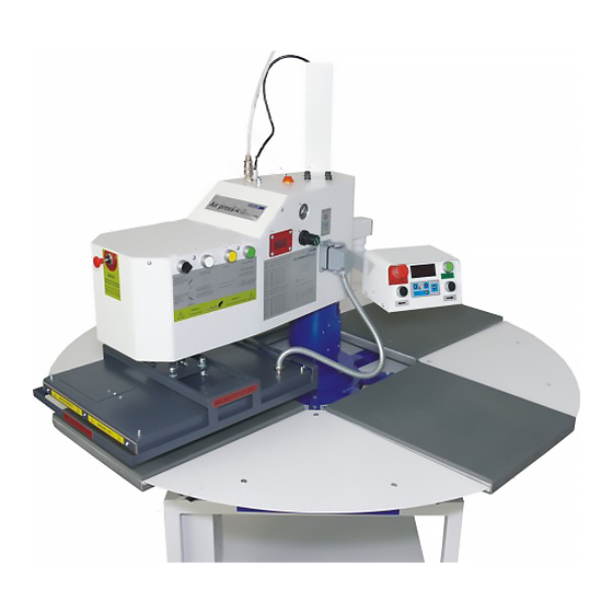
Page 3: Illustration Of The Heat Press
1.2 Illustration of the heat press Heating plate with safety frame 12. Control desk Emergency button 13. Spiral tube Switch manual / automatic 14. Base plate with silicon rubber Activation safety frame 15. Cover plate Counter switch 16. Rotation of the base plate to the left Program change switch 17. -
Page 4: Technical Data
21. Metal case 25. Retainer 22. Air filter with water separator 26. Power cable 23. Main fuse 27. Compressed air connection 24. Main switch 28. Electric case 1.3 Technical data Dimensions of the press with metal case: 182 x 146 x 146 cm Working area: 40 x 50 cm / 38 x 50 cm Weight:... -
Page 5: Accessory
1.4 Accessory The Air press-4 X can be equipped with complementary accessory. 1. Cooling system 3. Laser with mounting 2. Screen print frame mounting 1.5 Exchangeable heating plates For the press there are several heating plates available. The instruction for the exchange you can find in chapter 3.7. -
Page 6: Safety Arrangements Of The Press
The testing should be protocoled. If any irregularities regarding functionality or safety are found during the testing, these have to been noted and reported to Walter Schulze GmbH in written form within 7 days. Until clarification the press can not be used. -
Page 7: Initiation
2.1 Tips for transport The SCHULZE Air press-4 X is covered in protective foil for transport and fixed onto the pallet. Right after the receiving you should check if the foil and the press are in good condition. Later on, if you have to send the press somewhere, we ask you to fix the press in the same way on the pallet. - Page 8 Assembly instruction of the base plates: Put the base plates in place (photo 1-2) Tighten the base plates (photo 3-4) Assembly instruction of the heating plate: Put the heating plate on the base plate (photo 1) Pick up the heating plate and then put into the pin (photo 2) Screw the heating plate (photo 3) Connect the heating plate with the press (photo 4-5) Version 11.01...
-
Page 9: Connection Of The Press To Compressed Air
2.4 Power supply Die Air press-4 X has to be connected to a voltage of 230VAC/ 50Hz. The press is equipped with a plug. Make sure that the power outlet is in the right condition and that the grounding is connected to the power outlet. Turn and fasten the the retainer (photo 1-2). An extension cable 230VAC must be fasten in the retainer above the press (photo 3-4). -
Page 10: Initiation Of The Heat Press
2.5 Initiation of the heat press The press should only be used by trained personal after notice of this manual. Before the first start up m ake sure that the power outlet is in the right condition and that the grounding is connected to the power outlet. Assemble the press before you work with it (chapter 2.2). The press can be turned on with the green dip-switch (photo 1). -
Page 11: Working With The Heat Press
3. Working with the heat press 3.1 Programming the electronic devices After switching on the press, the current temperature is shown is shown on the display and the press heats up. Change settings: The programming mode shows up when you press Setup for about 5 seconds, until the LED1 blinks up. LED1 blinks and the programmed temperature shows on the display The programming mode is activated. -
Page 12: Counter
3.3 Counter Air Press-4 X is equipped with a transfer counter. The number of transfers is displayed on the screen. Use the yellow button (picture 1) to reset the counter or deduct one unit from the counter’s record. Additionally, the screen (picture 2) displays the number of the selected program. -
Page 13: Pressure Settings
3.6 Pressure settings Wit this press you can change the pressure setting . After every change of the pressure settings, close the heat press to check the new settings. Damages, which arise from to much pressure, are excluded from the guarantee. To adjust the pressure do the following: Take the pressure reading. -
Page 14: Exchanging The Heating Plate
3.7 Exchanging the heating plate To exchange the heating plate, the press must be disconnected from electricity and cold. Now disconnect the spiral tube plug of the heating plate. (photo 1-2). Loosen fixation screw with a wrench (photo 3). Take hold of the plate and put it down carefully on the base plate (photo 4-5). -
Page 15: Safety Frame
3.9 Safety frame The Air press-4 X is equipped with an safety frame (photo 1). The safety frame guards against burnings. If you should touch the safety frame while it's going down (photo 2), the process will be interrupted at once. In that case you have to press the activation button again (photo 3). -
Page 16: Screen Printing Mounting Adjustment (Optional)
3.11 Screen printing mounting adjustment (optional) At the Airpress4 you can mount a screen print frame directly over one of the base plates. In this way you can print one colour directly on the press. To work comfortably with the frame you can adjust the screen lift-off (photo 2 + 3) and the inclination of the screen (photo 4) with the depicted screws 4. -
Page 17: Replacing The Main Fuse
4.2 Replacing the main fuse If the heat press does not work after switching on (the main switch is glowing, but the display is not), check the main fuse of the press. The main fuse 12A is placed in the upper part of the press (photo 1). To exchange the fuse, switch off the heat press first and pull the plug. -
Page 18: Replacing The Fuse In The Power Supply
4.4 Replacing the fuse in the power supply The heat press is equipped with a main fuse 1,6A/12Volt, which is placed in the upper part of the press. In the electric case is a LED. When the LED (photo 1) glows, the power supply works. If the LED doesn't glows, the fuse 1,6A in the power supply has to be exchanged. - Page 19 4.6 Electronics keyboard replacement To change the electronics keyboard the press must be switched off and unplugged. Remove the electronics from the control panel as instructed in chapter 4.5. Disconnect the keyboard plug from the electronics (picture 1) and remove the keyboard from the press (picture 2).
-
Page 20: Replacing The Silicon Mat
4.8 Transmitter replacement If the lower platens do not change position after pushing the right/left platen turn button, check if the diodes on the transmitter are on (turn of the platens left – the left transmitter; turn of the platens right – the right transmitter) (picture 1). If the diodes are not on, a given transmitter is broken and needs to be replaced (picture 2-3). -
Page 21: Replacing The Thermo Couple
4.11 Replacing the thermo couple The replacing may only be done by an authorized person. For the replacement of the thermo couple the press must be disconnected from the electricity and cold. Remove the cap and take out isolation.. (photo 1) Remove the thermo couple. -
Page 22: Troubleshooting
Reset the electronic devices, but Malfunction of the electronic devices Temperature on the display – Temperature too high/low first contact Walter Schulze GmbH The press heats up very slowly – over 30 minutes One of the tow heating elements is defect... -
Page 23: Connection Diagram
4.13 Connection diagram Version 11.01 23/26... -
Page 24: Controlling Of The Pneumatics
4.14 Controlling of the pneumatics Version 11.01 24/26... -
Page 25: Certificate Of Manufacturer
4.15 Certificate of manufacturer Version 11.01 25/26... -
Page 26: Testing Report
EN ISO 12100-1 EN ISO 12100-2 safety of machines EN 60204-1 electrical equipment of machines Berlin , .._____________________________ Peter Meidinger President All SCHULZE heat presses are exempt from the waste disposal law under reg. no. DE 231060054. Version 11.01 26/26...
Need help?
Do you have a question about the Air press-4 X and is the answer not in the manual?
Questions and answers