Advertisement
Quick Links
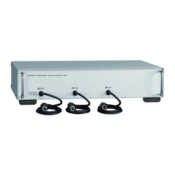
PW9100-03
PW9100-04
AC/DC CURRENT BOX
Instruction Manual
Dec. 2015 Edition 1
Printed in Japan
PW9100A961-00 15-12H
Warranty
Warranty malfunctions occurring under conditions of normal use in
conformity with the Instruction Manual and Product Precautionary
Markings will be repaired free of charge. This warranty is valid for
a period of one (1) year from the date of purchase. Please contact
the distributor from which you purchased the product for further
information on warranty provisions.
Introduction
Thank you for purchasing the Hioki PW9100-03, PW9100-04 AC/
DC Current Box. To obtain maximum performance from the device,
please read this manual first, and keep it handy for future reference.
Verifying package contents
When you receive the device, inspect it carefully to ensure that
no damage occurred during shipping. In particular, check the
accessories and connectors. If damage is evident, or if it fails to
operate according to the specifications, contact your authorized
Hioki distributor or reseller.
Cleaning
To clean the device, wipe it gently with a soft cloth moistened with
water or mild detergent.
Calibrations
The calibration period varies depending on the status of the device
or installation environment. We recommend that the calibration
period be determined in accordance with the status of the device
or installation environment. Please contact your Hioki distributor to
have your device periodically calibrated.
Find Quality Products Online at:
Troubleshooting
If the device seems to be malfunctioning, contact your authorized
Hioki distributor or reseller.When sending the device for repair, be
sure to include details of the problem.
Discarding the device
Handle and dispose of the device in accordance with local
regulations.
Overview
EN
This device measures AC and DC currents of up to 50 A with a high
degree of precision. Thanks to its excellent frequency characteristics
(amplitude and phase) and temperature characteristics (sensitivity
and offset), it can be used not only for current measurement, but
also for high-precision power measurement.
Names of Parts
Front panel
Rear panel
Safety Information
This device is designed to conform to IEC 61010 Safety Standards,
and has been thoroughly tested for safety prior to shipment.
However, using the device in a way not described in this manual
may negate the provided safety features.
Before using the device, be certain to carefully read the following
safety notes:
GlobalTestSupply
www.
CH A
CH B
CH C
Current input terminals
CH D
CH C
Affix channel number
Safety cover
sticker here.
The above figure depicts the PW9100-04 (4-channel model).
DANGER
Mishandling during use could result in injury
or death, as well as damage to the device. Be
certain that you understand the instructions and
precautions in the manual before use.
.com
Output cables
CH D
CH B
CH A
GND
sales@GlobalTestSupply.com
Advertisement

Related Manuals for Hioki PW9100-03


Summary of Contents for Hioki PW9100-03
- Page 1 Troubleshooting If the device seems to be malfunctioning, contact your authorized PW9100-03 Hioki distributor or reseller.When sending the device for repair, be sure to include details of the problem. PW9100-04 Discarding the device Handle and dispose of the device in accordance with local AC/DC CURRENT BOX regulations.
- Page 2 (≤600 V) Outlet screws or find that any screws are damaged, Power meter please contact your Hioki distributor for a Fixed installation replacement. For more information, see the power meter’s instruction manual. This device may cause interference if used in residential areas.
- Page 3 EIA and JIS power meter settings and precautions, refer to the instruction variants. For more information, please contact your manual for the power meter being used. authorized Hioki distributor or reseller. External dimensions Power meter (rear of PW6001) 430 ±2 mm...
- Page 4 700 kHz < f ≤ 1 MHz Accessories Channel number stickers, color labels, instruction ±4% rdg. ±(0.03 × f) deg. manual, tie bands (PW9100-03: 3; PW9100-04: 4) Options CT9901 Conversion Cable (for connecting to the 3390 or 300 µV rms or less (≤1 MHz) Output noise 3390-10) and CT9902 Extension Cable (5 m) Effects of temperature Within the range of 0°C to 18°C or 28°C to 40°C...
Need help?
Do you have a question about the PW9100-03 and is the answer not in the manual?
Questions and answers