Sign In
Upload
Download
Table of Contents
Contents
Add to my manuals
Delete from my manuals
Share
URL of this page:
HTML Link:
Bookmark this page
Add
Manual will be automatically added to "My Manuals"
Print this page
×
Bookmark added
×
Added to my manuals
Manuals
Brands
Amazone Manuals
Farm Equipment
Cenius 3003
Operating manual
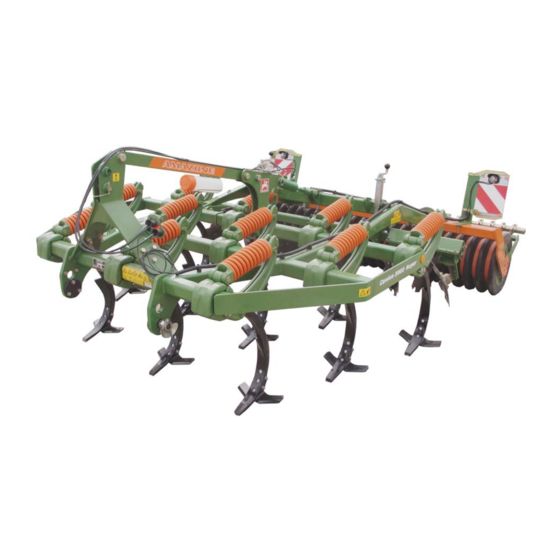
Amazone Cenius 3003 Operating Manual
Mounted cultivator
Hide thumbs
1
2
3
4
Table Of Contents
5
6
7
8
9
10
11
12
13
14
15
16
17
18
19
20
21
22
23
24
25
26
27
28
29
30
31
32
33
34
35
36
37
38
39
40
41
42
43
44
45
46
47
48
49
50
51
52
53
54
55
56
57
58
59
60
61
62
63
64
65
66
67
68
69
70
71
72
73
74
75
76
77
78
79
80
page
of
80
Go
/
80
Contents
Table of Contents
Bookmarks
Table of Contents
Table of Contents
1 User Information
Purpose of the Document
Locations in the Operating Manual
Diagrams Used
2 General Safety Instructions
Obligations and Liability
Representation of Safety Symbols
Organisational Measures
Safety and Protection Equipment
Informal Safety Measures
User Training
Safety Measures in Normal Operation
Dangers from Residual Energy
Maintenance and Repair Work, Fault Elimination
Constructive Changes
Spare and Wear Parts and Aids
Cleaning and Disposal
User Workstation
Warning Pictograms and Other Signs on the Machine
Positioning of Warning Pictograms and Other Labels
Dangers of Not Observing Safety Instructions
Safety-Conscious Working
Safety Information for Users
General Safety and Accident Prevention Information
Hydraulic System
Electrical System
Cleaning, Maintenance and Repairs
3 Loading and Unloading
4 Product Description
Overview of Subassemblies
Safety and Protection Equipment
Transportation Equipment
Intended Use
Danger Area and Danger Points
Rating Plate and CE Marking
Technical Data
Necessary Tractor Equipment
Noise Production Data
5 Structure and Function
Tines
Coulter
Coulter C-MIX
Coulter Arrangement
Levelling Unit
Cenius 3503: Adjustment - Concave Discs
Boundary Discs / Side Closer
Rollers
Rear Harrow (Optional)
Hydraulic Connections
Connecting Hydraulic Hoses
Disconnecting Hydraulic Hoses
Three-Point Hitch Frame
6 Commissioning
Checking the Suitability of the Tractor
Calculating the Actual Values for the Total Tractor Weight, Tractor Axle Loads and Load Capacities, as Well as the Minimum Ballast
Securing the Tractor/Machine against Unintentional Start-Up and Rolling
7 Coupling and Uncoupling the Machine
Coupling the Machine
Uncoupling the Machine
8 Adjustments
Working Depth of the Tines
Mechanical Depth Adjustment
Hydraulic Depth Adjustment
Working Depth of the Levelling Unit
Setting the Working Depth of the Levelling Unit Mechanically
Setting the Working Depth of the Levelling Unit Hydraulically
Adjusting the Stripper
9 Transportation
10 Use of the Machine
Changing from Transport to Working Position
Operation
Headland
11 Faults
12 Cleaning, Maintenance and Repairs
Cleaning
Lubrication Instructions
Maintenance Plan - Overview
Coulter Replacement and Tine Replacement
Tine Replacement
Coulter Replacement
Coulter Replacement C-MIX-Clip
Installing and Removing the Disc Segments (Workshop Work)
Replacing Discs (Workshop Work)
Tine Connection
Checking the Roller
Disc Carrier Connection
Hydraulic System (Workshop Work)
12.10.1 Labelling Hydraulic Hose Lines
12.10.2 Maintenance Intervals
12.10.3 Inspection Criteria for Hydraulic Hose Lines
12.10.4 Installation and Removal of Hydraulic Hose Lines
Lower Link Pins
13 Hydraulic Circuit Diagram
Screw Tightening Torques
Advertisement
Quick Links
Download this manual
Special
MG5552
BAG0144.5 10.19
Printed in Germany
en
Operating Manual
az
Mounted cultivator
Cenius 3003
Cenius 3503
Cenius 4003
Super
Read and observe this
operating manual before using
the machine for the first time!
Keep it in a safe place for
future use!
Table of
Contents
Previous
Page
Next
Page
1
2
3
4
5
Advertisement
Table of Contents
Need help?
Do you have a question about the Cenius 3003 and is the answer not in the manual?
Ask a question
Questions and answers
Related Manuals for Amazone Cenius 3003
Farm Equipment Amazone Centaya 3000 Super 1600 Operating Manual
Pneumatic pack top seed drill (230 pages)
Farm Equipment Amazone Cenius 3503 Operating Manual
Mounted cultivator (80 pages)
Farm Equipment Amazone Cenius 4003 Operating Manual
Mounted cultivator (80 pages)
Farm Equipment Amazone Cenius Super Operating Manual
Mounted cultivator (80 pages)
Farm Equipment Amazone Cenius Special Operating Manual
Mounted cultivator (80 pages)
Farm Equipment Amazone Centaya Operating Manual
Isobus software seed drill (60 pages)
Farm Equipment Amazone Centaur 6001 Quick Manual
(2 pages)
Farm Equipment Amazone Centaur 3002 Instruction Manual
(40 pages)
Farm Equipment Amazone Cenius 4003-2TX Operating Manual
Mulch cultivator (108 pages)
Farm Equipment Amazone Cenio 3000 Operating Instructions Manual
(98 pages)
Farm Equipment Amazone Centaur 4002 Instruction Manual
(40 pages)
Farm Equipment Amazone Cayros M Original Operating Manual
Mounted reversible plough with pendulum support wheel / double support wheel / without support wheel (104 pages)
Farm Equipment Amazone Cirrus Series Operating Manual
(209 pages)
Farm Equipment Amazone Cataya 3000 Super Operating Manual
Mechanical pack top seed drill (168 pages)
Farm Equipment Amazone Catros 4003-2 Original Operating Manual
Mounted compact disk harrow (88 pages)
Farm Equipment Amazone Citan 6000 Operating Instructions Manual
Seed drill (212 pages)
This manual is also suitable for:
Cenius 3503
Cenius 4003
Cenius super
Cenius special
Table of Contents
Print
Rename the bookmark
Delete bookmark?
Delete from my manuals?
Login
Sign In
OR
Sign in with Facebook
Sign in with Google
Upload manual
Upload from disk
Upload from URL


Need help?
Do you have a question about the Cenius 3003 and is the answer not in the manual?
Questions and answers