
Subscribe to Our Youtube Channel
Related Manuals for Drucker Diagnostics 642M


Summary of Contents for Drucker Diagnostics 642M
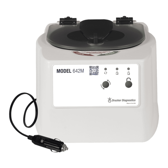
- Page 1 200 Shadylane Drive Philipsburg, PA 16866 www.druckerdiagnostics.com Service Manual 642M CENTRIFUGE DRUCKER DIAGNOSTICS SM023 642M SERVICE MANUAL REV C...
-
Page 2: Table Of Contents
Contents PREFACE GENERAL DESCRIPTION OF MAJOR COMPONENTS WARRANTY INFORMATION SPECIFICATIONS TROUBLESHOOTING SERVICE INSTRUCTIONS WIRING DIAGRAM SPARE PARTS LIST DRUCKER DIAGNOSTICS SM023 642M SERVICE MANUAL REV C... -
Page 3: Preface
Failure to follow the procedures in this document may result in personal injury or instrument damage. Drucker Diagnostics will not be held liable for any injury or damage because of improper servicing. -
Page 4: Troubleshooting
POSSIBLE CAUSE SOLUTION Rotor speed is lower than Confirm source voltage meets or exceeds this value. Rotor speed is calibrated at 13.8 VDC specified range Motor speed will vary according to source voltage. DRUCKER DIAGNOSTICS SM023 642M SERVICE MANUAL REV C... -
Page 5: Service Instructions
Begin by unplugging the centrifuge and waiting 10 minutes for internal voltages to dissipate. • Use a #2 Phillips screwdriver to remove the cabinet screws (six on the bottom, three in the rear) DRUCKER DIAGNOSTICS SM023 642M SERVICE MANUAL REV C... - Page 6 The front panel assembly is held in place with ten locking tabs (fig 1). • Push the tabs inward to release the assembly. • To install the front panel assembly, push it into the opening in the cabinet until it snaps into place. Figure 1 DRUCKER DIAGNOSTICS SM023 642M SERVICE MANUAL REV C...
- Page 7 Make certain that the motor wires are in the notch, and that no wires are pinched between the guard bowl and base. • Fasten the guard bowl to the base with the six screws and connect the wires as shown in the wiring diagram. DRUCKER DIAGNOSTICS SM023 642M SERVICE MANUAL REV C...
- Page 8 Carefully place the cabinet onto the base taking care not to pinch any wires between the two. • Complete the assembly by replacing the six screws in the bottom and three in the rear. DRUCKER DIAGNOSTICS SM023 642M SERVICE MANUAL REV C...
-
Page 9: Wiring Diagram
7. WIRING DIAGRAM DRUCKER DIAGNOSTICS SM023 642M SERVICE MANUAL REV C... -
Page 10: Spare Parts List
8. SPARE PARTS LIST DRUCKER DIAGNOSTICS SM023 642M SERVICE MANUAL REV C...
Need help?
Do you have a question about the 642M and is the answer not in the manual?
Questions and answers