Husqvarna K7000 Workshop Manual
Hide thumbs
Also See for K7000:
- Operator's manual (128 pages) ,
- Workshop manual (36 pages) ,
- Operator's manual (92 pages)
Advertisement
Advertisement

Related Manuals for Husqvarna K7000


Summary of Contents for Husqvarna K7000
- Page 1 Workshop manual K7000 HUSQVARNA CONSTRUCTION PRODUCTS...
-
Page 2: Table Of Contents
CONTENTS Page HUSQVARNA 1. DOCUMENTATION 2. COMPONENTS – NAVIGATION K7000 3. CONTROLS, ELECTRICAL COMPONENTS 4. MOTOR 5. CUTTING HEAD 6. WET SYSTEM 7. TROUBLESHOOTING 8. TOOLS... -
Page 3: Documentation
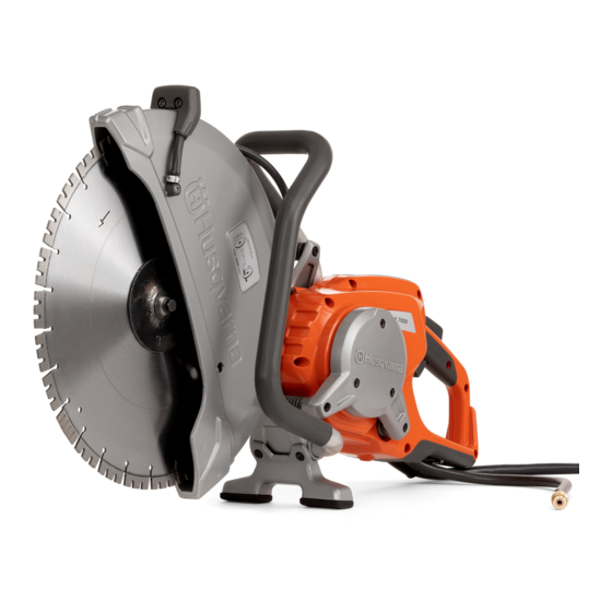
DOCUMENTATION Workshop manual This workshop manual covers virtually all work in the workshop that involves the K7000. Some very simple and rather obvious repair work has been omitted. Arrangement – illustrations and text This manual is divided into numbered chapters as well as chapter headings that are specified in bold at the top of each page. - Page 4 Components 1. Cutting blade 2. Blade guard 3. Adjustment handle for the blade guard 4. Front handle 5. Motor guard 6. Water valve 7. Motor bracket 8. Throttle 9. Rear handle 10. Starter lock 11. Valve – cooling water 12. Display 13.
-
Page 5: Controls, Electrical Components
CONTROLS, ELECTRICAL COMPONENTS Removal Rear motor guard Remove the screws indicated with arrows, then remove the guard. (7 x MT5x14, 3–4 Nm. 1 x MT5x40, 3–4 Nm) When the guard has been removed, most components are accessible, such as the control unit with electrical connections, the water valve and hoses. - Page 6 CONTROLS, ELECTRICAL COMPONENTS 1. The yellow cable on the right is removed by undoing the locking screw on the top. 2. The grey cable on the left is locked with a spring. Insert a small screwdriver in the recess just to the right of the cable and pull this out.
-
Page 7: Motor
MOTOR Removal Front motor guard The front motor guard must be removed in order to access the motor itself and the electrical connections to it. First, remove the rear guard and the control unit as described on page 5. 1. Remove the vibration element's inner screw, 4 mm Allen. (3–4 Nm) 2. - Page 8 MOTOR Function Working method The way in which the high frequency motor works differs signifi- cantly from a traditional motor with rotor windings and collec- tor/carbon brushes. The rotor in the high frequency motor consists of permanent magnets with high magnetic force, known as neodymium magnets. In other words, the rotor has no windings or electrical components.
- Page 9 At this stage, the belt can be replaced. Cutting arm The K7000 has a cutting arm which is permanently fitted to the motor and has brackets to the handle unit with vibration elements. A damaged cutting arm can easily be replaced.
- Page 10 CUTTING HEAD Dismantling – blade guard/bearing housing Remove the cutting head from the machine as shown on the previous page. This section describes dismantling of the components in the cutting unit and ends with an instruction on how to replace the blade shaft bearings.
-
Page 11: Cutting Head
CUTTING HEAD Assembly – blade guard /bearing housing Make sure the rubber seal has the right fit in relation to the bearing housing and blade guard. Turn the bearing housing so that the screw holes are accessible from above with the tool. Fit the blade guard –... - Page 12 CUTTING HEAD Belt pulley Removal Attach the bearing holder in a vice with soft jaws. Lock the belt pulley rotation with a pin punch or a screwdriver. Remove the centre screw. Washer Note that there must be a washer on the upper side of the belt pulley.
- Page 13 CUTTING HEAD Blade shaft bearing housing The bearing housing carries dual ball bearings for the blade's drive shaft. Blade shaft, bearings The blade shaft has a fixed machined spacer which the bearings' inner rings must be in contact with after assembly in the bearing housing.
- Page 14 CUTTING HEAD Fitting with press Support the bearing housing under the area for the bearing with, for example, a piece of wood so that the bearing housing is horizontal. Put the bearing in place and position the pressing device C on top of the bearing.
-
Page 15: Wet System
WET SYSTEM Hose clips Oetiker system The machine is originally fitted mainly with a single-use Oetiker ear clip. This type of clip has the advantage of being able to give small- dimension hoses even clamping force all round with a minimal risk of leakage. - Page 16 WET SYSTEM Wet system Design A spray nozzle is located on each side of the blade guard. The water strikes a section of the cutting blade and the centrifugal force carries it out towards the blade's diamond segment. The spray nozzles are available with several different hole diameters depending on the type of machine and application.
- Page 17 WET SYSTEM Water valve Function The motor requires water cooling so as not to overheat. The water is fed from the water valve to the motor's cooling ducts, and nor- mally on to the spray nozzles on the blade guard. If dry cutting is necessary, the flow is rerouted, and the water is fed to the hose beneath the rear handle once it was cooled the motor.
-
Page 18: Troubleshooting
Defective HF unit or cutting machine? When troubleshooting, it is important to remember that the fault may be in either the cutting machine K7000 or the unit PP70. If you have access to another working PP70 and machine, these can be used in order to identify the faulty unit. - Page 19 TROUBLESHOOTING Motor Dismantle the cutting machine so that the motor's connectors are accessible. The motor does not need to be removed from the machine. Short-circuit testing Check first to make sure that the motor does not have shorted windings to earth (motor material). This is easy to do using a multimeter on the contact X1.
- Page 20 If measured values are outside the tolerance ranges, the ther- mistor is defective. Cable between PP70 and K7000 Supply cables which have been “driven over” or abused are a relatively common cause of interference. Carry out a visual check of the outside of the cable for damage due to trapping.
- Page 21 TROUBLESHOOTING Signal cables, connection testing and insulation testing This test is used to check whether any cable is broken and whether there is any damaged insulation which is causing the wires to come into contact with one another. This test is carried out with a multimeter set for connection testing with a buzzer signal.
- Page 22 The special tools below are needed for servicing work on the K7000 but are not sold by Husqvarna: Insulation and continuity tester Common makes: Megger, Fluke, etc. ● Checking of the motor's windings and cabling Tachometer A number of optical tachometer makes are available.
- Page 24 www.husqvarnacp.com 114 21 66-26 English 2013-09...
Need help?
Do you have a question about the K7000 and is the answer not in the manual?
Questions and answers