
Subscribe to Our Youtube Channel
Related Manuals for HMS Anybus-X AB7609


Summary of Contents for HMS Anybus-X AB7609
- Page 1 Anybus-X PROFIBUS to DeviceNet Gateway User Manual Part No. AB7609 Rev 1.21 HMS Industrial Networks Pilefeltsgatan 93-95 SE-302 50 Halmstad Sweden Phone +46 (0) 35 17 19 00 Web www.Anybus.com AB7609 User manual...
-
Page 2: Table Of Contents
Step By Step Configuration ........4-1 PROFIBUS Network Configuration ......4-1 DeviceNet Network Configuration ......4-2 DeviceNet I/O Configuration........4-10 PROFIBUS Interface..........5-1 Network Communication ..........5-1 Device Diagnostics............. 5-2 Interaction with I/O Tables ......... 5-2 © 2005 HMS Industrial Networks AB7609 User manual... - Page 3 I/O Data Sizes ............8-3 Connectors ..............9-1 Power ................. 9-1 DeviceNet..............9-2 PROFIBUS ..............9-3 Auxiliary RS-232 ............9-4 Warranty ..............10-1 Support ..............11-1 Technical Product Assistance ........11-1 Contact Information ..........11-1 © 2005 HMS Industrial Networks AB7609 User manual...
-
Page 4: Preface
The information in this document is subject to change and should not be considered as a commitment by HMS Industrial Networkss. HMS Industrial Networkss assumes no responsibility for errors that may appear in this document There are many applications of the Anybus-X module. -
Page 5: Related Documentation
Preface v Related Documentation Document Name Author Web Page DeviceNet Specification ODVA www.odva.org PROFIBUS Specification PROFIBUS International www.profibus.com Table 1-1 Related Documentation © 2005 HMS Industrial Networks AB7609 User manual... -
Page 6: Anybus-X Module Description
No special, or extended, protocol features are required of the devices on either network to read or write the data flowing through the Passage- Way; all cross-network activity is transparent to the devices on either network. © 2005 HMS Industrial Networks AB7609 User manual... -
Page 7: Devicenet Features
Combined with Automatic Address Recovery this feature is known as Automatic Device Recovery (ADR). PROFIBUS Features • PROFIBUS-DP slave. • Cyclic I/O data transmission. • Device diagnostic transmission. • Baud rates ranging from 9.6 Kbps to 12 Mbps. © 2005 HMS Industrial Networks AB7609 User manual... -
Page 8: System Requirements
24 VDC power connection • PC to execute DeviceNet Configuration Software. The DeviceNet scanner configuration is done using DeviceNet configuration software tool such as RSNetWorx for DeviceNet from Rockwell Software or HMS NetTool- Optional Hardware • DIN rail to mount the Anybus-X. -
Page 9: Hardware Description
PROFIBUS interface. See “Status and Diagnostics” Page 7-1 for details on how the LEDs are used. The back of the module has a DIN rail mount to allow the module to be mounted on a DIN rail. © 2005 HMS Industrial Networks AB7609 User manual... -
Page 10: Installation
•Terminal tightening torque must be between 5-7 lbs-in (0.5-0.8 Nm). •For use in Class 2 circuits only. •Suitable for surrounding temperature of 65 degrees C maximum. •Use 60/75 C copper wire only. © 2005 HMS Industrial Networks AB7609 User manual... -
Page 11: Power And Network Connections
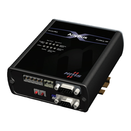
The power and network connections to the AnyBus-X are made on the end of the module. Figure 2-1 indicates the location of each connector. DeviceNet Power Aux RS-232 PROFIBUS PROFIBUS PROFIBUS Address Termination Figure 2-1 AnyBus-X Power and Network Connections © 2005 HMS Industrial Networks AB7609 User manual... -
Page 12: Connecting Power
24VDC Common 24 VDC + Figure 2-2 Power Connection The AnyBus-X requires 24 volts DC power. The module will start immediately when power is applied (There is no On/Off switch on the module). © 2005 HMS Industrial Networks AB7609 User manual... -
Page 13: Connecting Devicenet
See the DeviceNet Specification for specific rules on DeviceNet connections and termination. For information on setting the DeviceNet network configuration (MAC ID, baud rate, etc.), see “ABX Configuration Tool (BWConfig)” on page 3-3. © 2005 HMS Industrial Networks AB7609 User manual... -
Page 14: Connecting To Profibus
In typical applications only the A-Line, B-Line and Shield connections are used. For information on setting the PROFIBUS network configuration (address, baud rate, etc.), see “PROFIBUS Network Configuration” on page 3-1. © 2005 HMS Industrial Networks AB7609 User manual... -
Page 15: Configuration
The Anybus-X has automatic baud rate detection so no configuration of the Anybus-X itself is required. 9.6 Kbps 1.5 Mbps 19.2 Kbps 3 Mbps 93.75 Kbps 6 Mbps 187.5 Kbps 12 Mbps 500 Kbps Table 3-1 Supported PROFIBUS Baud Rates © 2005 HMS Industrial Networks AB7609 User manual... - Page 16 PROFIBUS master. The latest version of the GSD file for the Anybus-X can be downloaded from HMS Industrial Networks’s web site, or received by contacting HMS Industrial Networks. © 2005 HMS Industrial Networks...
- Page 17 Null-Modem (pins 2 and 3 swapped) serial cable between the PC serial port and the 9-pin D-Sub connector on the module. It does not matter which PC serial port you use, BWConfig will scan each available port and detect the connection auto- matically. © 2005 HMS Industrial Networks AB7609 User manual...
- Page 18 BWConfig tool bar; this will cause the tool to rescan the serial ports for a module. BWConfig User Interface The Anybus-X Configuration Tool’s user interface is shown in Figure 3-1. Figure 3-1 BWConfig User Interface © 2005 HMS Industrial Networks AB7609 User manual...
- Page 19 Send the configuration shown on the tool’s user interface to the Anybus-X module. Offline Configuration Offline configuration will allow a configura- tion to be created and saved without being connected to a module. © 2005 HMS Industrial Networks AB7609 User manual...
- Page 20 Configuration 3-6 Flash Update Perform a field upgrade of the Anybus-X module’s firmware. Note: Care should be taken when upgrading firmware, an incomplete update could cause irreparable harm to the module. © 2005 HMS Industrial Networks AB7609 User manual...
-
Page 21: Devicenet Network Configuration
PROFIBUS, which expects data to be stored in reverse byte orientation from DeviceNet. Table 3-3 DeviceNet Network Configuration Parameters Note: The Anybus-X will automatically reset after the DeviceNet configuration is downloaded from BWConfig. © 2005 HMS Industrial Networks AB7609 User manual... - Page 22 RSNetWorx or NetTool-DN, during configuration of the net- work. The laster version of the EDS file for the Anybus-X can be downloaded from HMS’s web site, or received by contacting HMS Networks AB. © 2005 HMS Industrial Networks AB7609 User manual...
-
Page 23: Devicenet I/O Configuration
244 bytes. If an I/O configuration is saved that exceeds the size limitations, the Anybus-X status and PROFIBUS diagnostics will indicate that there is an I/O size configura- tion error. © 2005 HMS Industrial Networks AB7609 User manual... - Page 24 The next chapter provides an example application, and covers the use of Rockwell Software’s RSNetWorx for DeviceNet and HMS’ NetTool-DN. © 2005 HMS Industrial Networks AB7609 User manual...
-
Page 25: Step By Step Configuration
Configuration” on page 3-1 for complete details on the network configuration. Figure 4-1 shows the network address set at 10 and the bus termination turned off. Figure 4-1 Example PROFIBUS Network Configuration © 2005 HMS Industrial Networks AB7609 User manual... -
Page 26: Devicenet Network Configuration
Anybus-X’s MAC ID and baud rate. The fol- lowing sections explain how this is done using either Rockwell Software’s RSNet- Worx for DeviceNet or HMS’ NetTool-DN. Note: The Anybus-X defaults to 125K baud out of the box. If your DeviceNet net- work is not running at 125K baud, the Anybus-X must be powered up on a local network with the node commissioning tool at 125K baud. - Page 27 Step 3: Register the Anybus-X EDS file in RSNetWorx. RSNetWorx requires an electronic data sheet (EDS) to recognize a device and its capabilities. An EDS file is available on the HMS Industrial Networkss web site. The EDS file must be registered with RSNetWorx before configuration can con- tinue.
- Page 28 Note: The ABX will automatically reset if a new MAC ID is entered. If only the baud rate is changed the ABX must be power cycled before the new baud rate will take effect. Note: When the MAC ID is changed, the ABX’s I/O configuration is cleared. © 2005 HMS Industrial Networks AB7609 User manual...
- Page 29 Note: If the Anybus-X is the only master on the DeviceNet network, DO NOT enable autobaud. Automatic baud detection requires there to be traffic on the net- work, there is typically no traffic until the master establishes connections. © 2005 HMS Industrial Networks AB7609 User manual...
- Page 30 A message should appear in the Data received from device box saying the execution was completed. Note: Changes to the byte swapping option do not take effect until the module has been power cycled. © 2005 HMS Industrial Networks AB7609 User manual...
- Page 31 DeviceNet network. If this is the first time that Net- Tool-DN has been used with a Anybus-X, the Anybus-X’s icon will indi- cate “No EDS file registers for this device”. © 2005 HMS Industrial Networks AB7609 User manual...
- Page 32 Step 3: Register the Anybus-X EDS file with NetTool-DN NetTool-DN requires an electronic data sheet (EDS) to recognize a device and its capabilities. An EDS file is available on the HMS Industrial Networkss web site. The EDS file must be registered with NetTool-DN before configuration can con- tinue.
- Page 33 Note: If the ABX is the only master on the DeviceNet network, DO NOT enable autobaud. Automatic baud detection requires there to be traffic on the network, there is typically no traffic until the master establishes connections. © 2005 HMS Industrial Networks AB7609 User manual...
-
Page 34: Devicenet I/O Configuration
This shows the format of the Input table of the ABX. This is the format of the input data that will be sent to the PROFIBUS master. See “I/O Mapping” on page 3-9. © 2005 HMS Industrial Networks AB7609 User manual... - Page 35 The ABX will automatically switch to Run mode when the PROFIBUS master is connected. Note: Once the ABX is placed into Run mode, it will begin sending output data to the devices configured in its scan list. © 2005 HMS Industrial Networks AB7609 User manual...
- Page 36 Note: Automap is used in this example to for simplicity. In some cases, the user may wish to organize the I/O data in other ways. See the NetTool-DN manual for complete details on how to accomplish this. © 2005 HMS Industrial Networks AB7609 User manual...
- Page 37 Conflict” downloading parameter 2. This error message can be ignored. Note: Once the ABX is placed into Run mode, it will begin sending output data to the devices configured in its scan list. © 2005 HMS Industrial Networks AB7609 User manual...
-
Page 38: Profibus Interface
EN50170. Topology Master-Slave. Connector 9-pin D-Subminiature female. Cable Shielded twisted pair. Isolation The bus is galvanically isolated from the Anybus-X electronics. Termination Switch selectable internal bus termination. Table 5-1 PROFIBUS Physical Interface © 2005 HMS Industrial Networks AB7609 User manual... -
Page 39: Device Diagnostics
Input table. Data is always read from the beginning (offset 0) of the Input table. The data will be what was placed there by the last write to the Input table by the DeviceNet interface. © 2005 HMS Industrial Networks AB7609 User manual... - Page 40 Hence, all data in the I/O tables is assumed to be stored as little endian by the DeviceNet nodes. Care should be taken to make sure that the PROFIBUS master handles input data and transmits output data least significant byte first. © 2005 HMS Industrial Networks AB7609 User manual...
-
Page 41: Devicenet Interface
If the autobaud option is enabled, the module will detect the cur- rent network baud rate and set its baud rate accordingly before joining the net- work. If the option is disabled, the module will join the network with the configured baud rate. © 2005 HMS Industrial Networks AB7609 User manual... -
Page 42: Slave Device Communication
The Anybus-X also supports a background polling mechanism. A foreground to background polling ratio can be specified to allow polling of devices at certain scan cycle intervals. © 2005 HMS Industrial Networks AB7609 User manual... -
Page 43: I/O Message Types
Predefined Master/Slave Connection Set. Group 3 explicit messages destined for a group 2 only device that is configured as a slave to the Anybus-X will be intercepted and relayed to the slave. © 2005 HMS Industrial Networks AB7609 User manual... -
Page 44: Run/Idle Mode
See “DeviceNet Network Configuration” on page 4-2 for explanation of setting the Anybus-X Run/Idle mode using RSNetWorx or NetTool-DN. Note: When the Anybus-X is reset or powered up, it begins operation in Idle mode. © 2005 HMS Industrial Networks AB7609 User manual... -
Page 45: Automatic Device Recovery (Adr)
Address Recovery is completed, Configura- tion Recovery will configure the new device. 2. Configuration Recovery guarantees that the slave devices will always run the same configuration. © 2005 HMS Industrial Networks AB7609 User manual... -
Page 46: Interaction With I/O Tables
When input data is received on a slave’s I/O connection, it is copied to the Input table. This data is available to be read by the PROFIBUS interface and sent to the PROFIBUS master on the next data exchange. © 2005 HMS Industrial Networks AB7609 User manual... -
Page 47: Status And Diagnostics
Major unrecoverable faults are indicated by a series of green and red flashes. If the Anybus-X Status LED is flashing red and green for an extended period of time, count the number of red and green flashes and call technical support. © 2005 HMS Industrial Networks. AB7609 User manual... - Page 48 A fault that can be corrected and does minor fault. not require a Anybus-X reset has been detected. This is typically a configu- ration error. Table 7-3 DeviceNet Module Status LED States © 2005 HMS Industrial Networks AB7609 User manual...
- Page 49 Flashing Red at Hardware An error occurred while initializing the error PROFIBUS ASIC. Table 7-6 PROFIBUS Diagnostic LED States © 2005 HMS Industrial Networks AB7609 User manual...
-
Page 50: Profibus Device Diagnostic Data
PROFIBUS I/O size error. The input or output size, or both, resulting from the scan list configu- ration is invalid. Not used. Table 7-8 Anybus-X Module Status Bit Definitions © 2005 HMS Industrial Networks AB7609 User manual... - Page 51 Shared master has not made connection to the device. Shared master has not made the right type of connection to the device. ADR keeper error. CAN network disabled. CAN bus-off. No DeviceNet power. Table 7-9 Node Status Codes © 2005 HMS Industrial Networks AB7609 User manual...
- Page 52 • The Anybus-X is in Idle mode. • The DeviceNet network status is Offline. (DeviceNet interface fault) • The I/O sizes resulting from the current scan list configuration are invalid. © 2005 HMS Industrial Networks AB7609 User manual...
-
Page 53: Specifications
EN50082-2-EMC Generic Immunity Standard, Part 2 - Industrial Envi- ronment This product is intended for use in an industrial environment. Electrical Specifications DC Power Operating voltage: 7-32 VDC. Current Requirements: 105-110 mA at 24 VDC. © 2005 HMS Industrial Networks AB7609 User manual... -
Page 54: Mechanical Specifications
Specifications 8-2 Mechanical Specifications Mechanical Rating IP20/NEMA 1 Dimensions Figure 8-1 Anybus-X PROFIBUS to DeviceNet Gateway Mechanical Dimensions © 2005 HMS Industrial Networks AB7609 User manual... -
Page 55: I/O Data Sizes
• Maximum 244 bytes Output table size. • Combined Input and Output table size must not be more than 400 bytes. • There must be at least 1 byte of Input or Output data configured. © 2005 HMS Industrial Networks AB7609 User manual... -
Page 56: Connectors
Chapter 9 Connectors 9-1 Connectors Power Figure 9-1 Power Connector Connection 24 VDC + 24 VDC Common Table 9-1 Power Connector Pin Definitions © 2005 HMS Industrial Networks AB7609 User manual... -
Page 57: Devicenet
Connectors 9-2 DeviceNet Figure 9-2 DeviceNet Connector Connection 24 VDC Common CAN Low Shield CAN High 24 VDC Table 9-2 DeviceNet Connector Pin Definitions © 2005 HMS Industrial Networks AB7609 User manual... -
Page 58: Profibus
Connectors 9-3 PROFIBUS Figure 9-3 PROFIBUS Connector Connection Not used Not used B-Line GND Bus +5 V Bus Not used A-Line Not used Table 9-3 PROFIBUS Connector Pin Definitions © 2005 HMS Industrial Networks AB7609 User manual... -
Page 59: Auxiliary Rs-232
Auxiliary RS-232 Figure 9-4 Auxiliary RS-232 Connector Connection Not used Receive Data Transmit Data Not used Not used Not used Not used Not used Not used Table 9-4 Auxiliary RS-232 Pin Definitions © 2005 HMS Industrial Networks AB7609 User manual... -
Page 60: Warranty
Warranty 10-1 Warranty HMS Industrial Networks warrants all new products to be free of defects in material and workmanship when applied in the manner for which they were intended and according to HMS Industrial Networkss’ published information on proper installation. The Warranty period is one year from the date of shipment. -
Page 61: Support
Chapter 11 Support 11-1 Support Technical Product Assistance If you need to contact HMS Industrial Networks for technical assistance, ask for Anybus-X technical support at: +46 (0) 35 17 29 00 You can obtain technical assistance by email at: support@anybus.com.
Need help?
Do you have a question about the Anybus-X AB7609 and is the answer not in the manual?
Questions and answers