Nexans XPLORER Series Instructions Manual
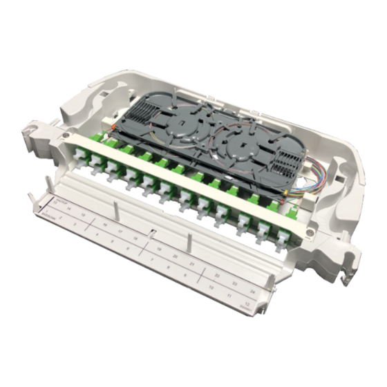
3u 128of splitter (sc and lc)
Hide thumbs
Also See for XPLORER Series:
- Instructions manual (21 pages) ,
- Instructions manual (29 pages)
Table of Contents
Advertisement
Quick Links
NOTICE / INSTRUCTIONS
XPLORER
XPLORER
Tous les schémas, dessins, spécifications, plans et détails de poids, tailles et dimensions figurant dans la
documentation technique ou commerciale de Nexans ont un caractère purement indicatif et ne sauraient
engager Nexans ou être traités comme constitutifs d'une garantie de la part de Nexans.
All drawings, designs, specifications, plans and particulars of weights, size and dimensions contained in the
technical or commercial documentation of Nexans is indicative only and shall not be binding on Nexans or be
3U - 128FO COUPLAGE (SC ET LC)
™
3U - 128OF SPLITTER (SC AND LC)
™
treated as constituting a representation on the part of Nexans.
Document : ABS1542/A
Date : 12/03/2019
Advertisement
Table of Contents

Related Manuals for Nexans XPLORER Series


Summary of Contents for Nexans XPLORER Series
- Page 1 All drawings, designs, specifications, plans and particulars of weights, size and dimensions contained in the technical or commercial documentation of Nexans is indicative only and shall not be binding on Nexans or be treated as constituting a representation on the part of Nexans.
-
Page 2: Table Of Contents
XPLORER™ Table des matières Table Of Contents DESCRIPTION OVERVIEW .......................4 1.1. PRÉSENTATION DU PRODUIT PRODUCT PRESENTATION ..................4 1.2. CARACTÉRISTIQUES TECHNIQUES TECHNICAL CHARACTERISTICS ................. 5 1.3. KITS FOURNIS PROVIDED KITS ......................6 FIXATION DU MODULE FIXATION OF THE MODULE ................7 2.1. - Page 3 XPLORER™ ÉLÉMENTS PARTICULIERS DE MAINTENANCE SPECIAL PROCEDURES FOR MAINTENANCE ..........22 6.1. REMPLACEMENT D’UN RACCORD ADAPTER REPLACEMENT ..................22 6.2. PRINCIPE DE DÉPOSE DU MODULE MODULE REPLACEMENT ..................23 6.3. REMPLACEMENT D’UN COUPLEUR SPLITTER REPLACEMENT ..................24 ANNEXES ANNEX ......................26 7.1. AUTRES KITS À APPROVISIONNER EN SUPPLÉMENT OTHERS KITS TO BE ORDERED SEPARATELY ............
-
Page 4: Description Overview
XPLORER™ DESCRIPTION OVERVIEW 1.1. Présentation du produit Product presentation Capot de protection Protective cover Peigne de fixation Fixation comb Équerre de fixation (dormant) Fixing bracket (fixed chassis) Zone de lovage Coiling area Goulotte pour la gestion des cordons Support for patchcords management Panneau frontal de brassage (128 FO) Front patch panel (128 OF) Plaque de verrouillage... -
Page 5: Caractéristiques Techniques Technical Characteristics
XPLORER™ 1.2. Caractéristiques techniques Technical characteristics – Poids : – Weight: – Hauteur : – Height: – Largeur : Standard 19”/ETSI – Width: 19”/ETSI standard – Profondeur : 185mm – Depth: 185mm ETSI 19’’ ABS1542/A 5/30... -
Page 6: Kits Fournis Provided Kits
XPLORER™ 1.3. Kits fournis Provided kits Qté / Description Kit de fixation 19’’ standard Standard 19’’ fixation kit (£↕9,5mm) : (£↕9.5mm): – Douilles – Sockets – Pions – Pawns – Plaque de verrouillage 19’’ 3U – Locking plate 19’’ 3U Kit de fixation 19’’... -
Page 7: Fixation Du Module Fixation Of The Module
XPLORER™ FIXATION DU MODULE FIXATION OF THE MODULE 2.1. Conditionnement Packaging Loquet Dormant Lock Fixed chassis Accessoires Accessories Battant Swiveling chassis ABS1542/A 7/30... - Page 8 XPLORER™ Mise en place du loquet côté Installing the lock to the opposite of opposé de l’axe de rotation. the rotation axis. ABS1542/A 8/30...
-
Page 9: Mise En Place Du Dormant Installing The Fixed Chassis
XPLORER™ 2.2. Mise en place du dormant Installing the fixed chassis Standard 19’’ Si l’armoire n’est pas conforme au Standard standard 19’’ £↕9,5mm, se reporter au chapitre 7 (annexes). Dimension carrés 9.5mm Squares dimension If the cabinet is not compliant with the 19’’... -
Page 10: Mise En Place De La Plaque De Verrouillage Installing The Locking Plate
XPLORER™ Sens de la douille et du pion sur le montant arrière. Position of the socket and the pawn in the back frame. Montant arrière Back frame Mise en place des pions(b). Installing pawns (b). Montant arrière Montant avant gauche Back frame Left front frame 2.3. -
Page 11: Mise En Place Du Battant Installing The Swiveling Chassis
XPLORER™ 2.4. Mise en place du battant Installing the swiveling chassis 90° Angle de montage repéré par un index moulé Mounting angle marked by molded index 90° Ne pas déclipper le battant après Do not unclip the swiveling chassis la mise en place. after the installation. -
Page 12: Raccordement Du Module Connection Of The Module
XPLORER™ Refermer le battant S’assurer du bon verrouillage Close the swiveling chassis Ensure to correct locking RACCORDEMENT DU MODULE CONNECTION OF THE MODULE 3.1. Raccordement par brassage Connection by patching oupleur : connection réseau par brassage Splitter: network connection by patching Coupleur Tronc préconnectorisé... -
Page 13: Raccordement Par Épissurage Connection Through Splicing
XPLORER™ Emplacement des troncs Tronc Cordon Inputs location Input Patchcord 3.2. Raccordement par épissurage Connection through splicing 3.2.1. Accès à l’organiseur Access to the organiser Veiller à bien dégager les Ensure to clear out the ergots ergots pour l’ouverture for the opening. 105°... -
Page 14: Préparation Du Câble Ou Du Pigtail Cable Or Pigtail Preparation
XPLORER™ Faire pivoter la platine Rotation of the plate 3.2.2. Préparation du câble ou du pigtail Cable or pigtail preparation Peigne métallique Metallic comb Cas 1 : préparation d’un pigtail Case 1: preparation of a pigtail Peigne métallique Pigtail Metallic comb Pigtail mm minimum 1500... -
Page 15: Fixation Arrière Du Pigtail, Micromodule Ou Loosetube Loosetube, Microbundle Or Pigtail Back Fixation
XPLORER™ Préparation du micromodule Preparation of the microbundle Peigne métallique Micromodule Metallic comb Microbundle Ø 5mm mm minimum Tube 1500 Préparation du loosetube Preparation of the loosetube Peigne métallique Fibres nues Metallic comb Bare fibres mm en sortie de loosetube 1000 3.2.3. -
Page 16: Cheminement Des Troncs Des Coupleurs Routing Of Splitters Inputs
XPLORER™ Cas 2: fixation d’un micromodule ou loosetube Case 2: fixation of the microbundle or loosetube Ø 5mm Micromodule ou loosetube Tube Microbundle or loosetube 3.2.4. Cheminement des troncs des coupleurs Routing of splitters inputs Coupleur Tronc préconnectorisé Branche Splitter Preterminated input Output Déconnecter le tronc du coupleur... - Page 17 XPLORER™ Cheminement des troncs: cas d’un tronc à souder pour un tiroir monté avec un axe à droite Routing of inputs: case of an input to be splice for a left axis module Coupleur Tronc Branche Splitter input Output Cheminement des troncs: cas d’un tronc à souder pour un tiroir monté avec un axe à gauche Routing of inputs: case of an input to be splice for a right axis module Coupleur Tronc...
-
Page 18: Cheminement Des Fibres Jusqu'à L'organiseur Routing Fibres Into The Organiser
XPLORER™ 3.2.5. Cheminement des fibres jusqu’à l’organiseur Routing fibres into the organiser Cas 1 avec les pigtails Case 1 with the pigtails Vue d’ensemble du câblage Cabling overview Pigtails Pigtails Fibres nues Bare fibres Pigtails Fibres nues raccordées (cassette supérieure) Tronc Pigtails Connected bare fibres (upper cassette) - Page 19 XPLORER™ Cas 2 avec les micromodules ou loosetubes Case 2 with the microbundles or loosetubes Peignes en mousse Peigne pour pigtails ou pour tubes Pigtails comb Foam or tubes combs Micromodule ou loosetube Fibres nues raccordées Fibres nues non raccordées Tronc Microbundle or loosetube Connected bare fibres...
-
Page 20: Fermeture Du Battant Closing The Swiveling Chassis
XPLORER™ FERMETURE DU BATTANT CLOSING THE SWIVELING CHASSIS Rabattre la platine et son capot Clipper le capot et resserrer la vis Rotate the plate and the cover Clip the cover and tighten the screw Refermer le battant swiveling chassis Close the ABS1542/A 20/30... -
Page 21: Pose D'un Cordon Installing Patchcord
XPLORER™ POSE D’UN CORDON INSTALLING PATCHCORD Ouvrir le volet de la goulotte et Insérer le cordon dans la goulotte connecter la fiche Insert the patchcord in the cableway Open the shutter of the cableway and connect the patchcord Passer le cordon dans l’anneau de guidage Refermer le volet Routing the patchcord in the spool clip Close the shutter... -
Page 22: Éléments Particuliers De Maintenance Special Procedures For Maintenance
XPLORER™ ÉLÉMENTS PARTICULIERS DE MAINTENANCE SPECIAL PROCEDURES FOR MAINTENANCE 6.1. Remplacement d’un raccord Adapter replacement Clip Clip Détrompeur vers le haut Polarising slot upwards ABS1542/A 22/30... -
Page 23: Principe De Dépose Du Module Module Replacement
XPLORER™ 6.2. Principe de dépose du module Module replacement Décâbler le module Unwire the module Vue de dessus Top view Retrait du pion du montant avant droit Remove pawn of the right front frame Retrait de la douille du montant avant droit Remove socket from the right front frame Si l’accessibilité... -
Page 24: Remplacement D'un Coupleur Splitter Replacement
XPLORER™ 6.3. Remplacement d’un coupleur Splitter replacement Retirer l’élastique Délover les branches du coupleur Remove the elastic Uncoil the splitter outputs Délover et couper l’épissure Déconnecter les branches du coupleur Disconnect the splitter outputs du tronc du coupleur Uncoil and cut the splice of the splitter input Retirer le coupleur Mise en place du nouveau coupleur... - Page 25 XPLORER™ Lover les branches du coupleur Lover et épissurer le tronc du coupleur Coil the splitter outputs Coil and splice the splitter input Mise en place de l’élastique Installing the elastic ABS1542/A 25/30...
-
Page 26: Annexes Annex
XPLORER™ ANNEXES ANNEX 7.1. Autres kits à approvisionner en supplément Others kits to be ordered separately Qté / Description Kit de fixation 19’’ (£↕9,5mm) : 19’’ fixation kit (£↕9.5mm): (À approvisionner en supplément) (To be ordered separately) – Écrous cages (£↕9,5mm) –... -
Page 27: Fixation Avec Écrous Cages Sur Montants 19'' Cage Nuts Fixation On 19'' Frames
XPLORER™ 7.2. Fixation avec écrous cages sur montants 19’’ Cage nuts fixation on 19’’ frames Utiliser les écrous cages £ ↕8,3mm ou Use cage nuts £↕8.3mm or £↕9.5mm if the £↕9,5mm dans le cas où l’utilisation du système utilisation of the pawns-sockets kit cannot be douilles-pions ne fonctionne pas. -
Page 28: Fixation Du Kit De Guidage Routing Kit Fixation
XPLORER™ 7.3. Fixation du kit de guidage Routing kit fixation Utiliser le kit de guidage dans le cas où les Use the routing kit if the cabinets are not armoires ne sont pas pourvues d’anneaux de provided with lateral routing rings. guidage latéraux. - Page 29 XPLORER™ Cas d’une armoire au format ETSI Cas d’une armoire au format 19’’ In the case of an ETSI cabinet In the case of a 19’’ cabinet Montage du kit bobine (e + j/d) Montage du kit bobine (d + e) Mounting spool kit (e + j/d) Mounting spool kit (d+ e) Montant avant gauche (c+ e + j/d)
-
Page 30: Instruction De Fin De Vie End Life Instruction
All drawings, designs, specifications, plans and particulars of weights, size and dimensions contained in the technical or commercial documentation of Nexans is indicative only and shall not be binding on Nexans or be treated as constituting a representation on the part of Nexans.
Need help?
Do you have a question about the XPLORER Series and is the answer not in the manual?
Questions and answers