Advertisement
Quick Links
■ F E A T R U E S
◎ A c c e p t D C / m A , D C / A , D C / m V , A C / A i n p u t s i g n a l , f i n i s h
t o t a l i z e r a n d c o n t r o l f u n c t i o n
◎ A c c u r a c y 0 . 1 % F . S . ± 1 d i g i t
◎ R a t e d i s p l a y r a n g e 0 t o 1 9 9 9 9 c a n b e m o d i f i e d
◎ T o t a l i z e r d i s p l a y r a n g e 0 t o 9 9 9 9 9 9 9 9 9
◎ R a t e a n d T o t a l i z e r d e c i m a l p o i n t c a n b e m o d i f i e d ◎ M a n - m a c h i n e i n t e r f a c e , e a s y t o o p e r a t e
◎ T o t a l i z e r t i m e b a s e c a n b e m o d i f i e d ( 1 / 6 0 / 3 6 0 0 s e c ) ◎ E E P R O M S a v i n g , d a t a s a f e k e e p i n g a b o u t 1 0 y e a r s
◎ S c a l e c a n b e m o d i f i e d ( 0 . 0 0 0 0 1 t o 9 9 9 9 . 9 9 9 9 9 )
◎ T o t a l i z e r o v e r a u t o m a t i c r e s e t
◎ T o t a l i z e r c a n b e s t o p c o u n t b y t e r m i n a l
◎ M a t h - r o o t e x t r a c t o r f u n c t i o n
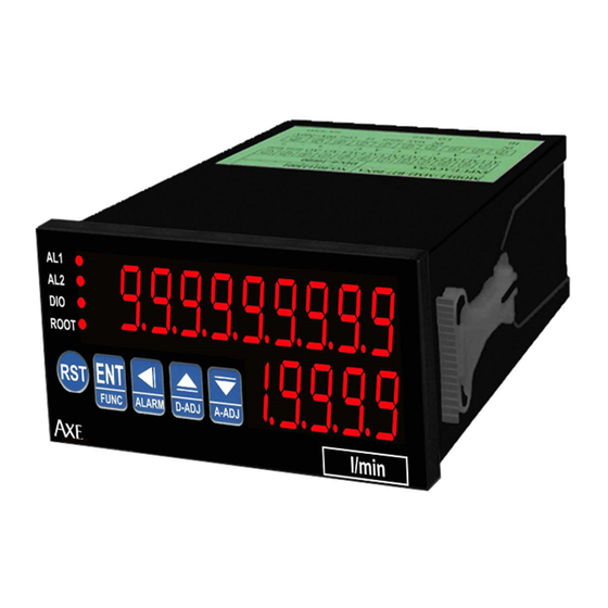
■ N a m e o f P a r t s
Alarm indicate
Communication indicate
Rootextractor indicate
■ A l a r m a c t i o n m o d e & C o n n e c t D i a g r a m D e s c r i p t i o n
1. ACT=HI,Display value≧Alarm value,Relay active,Display value<Alarm value,Relay reset
2. ACT=LO,Display value<Alarm value,Relay active,Display value≧Alarm value,Relay reset
3. RST Connect terminal function:When terminal RST&COM short about 200ms,Totalizer reset
4. GATE Connect terminal function:When terminal GATE&COM short about 200ms,Totalizer
stop count
5. ROOT Connect terminal function:When terminal ROOT&COM short about 200ms,Input
Rootextractor action
■ A n a l o g o u t p u t f u n c t i o n j u m p e r t a b l e
4 3 2 1
AXE Microprocess Rate & Totalizer Controller Meter
AL1
AL2
DIO
ROOT
ENT
E
RST
FUNC
ALARM
Cursor shift(Alarm adjustment call out)
Parameter ENTER(Function call out)
Totalizer Reset
Position 1&3 ON: DC 4~20 mA OUTPUT
Position 2&4 ON: DC 0~10V OUTPUT
◎ 1 5 B I T D A C a n a l o g o u t p u t c a n b e m o d i f i e d , 0 ~ 1 0 V
/ 4 ~ 2 0 m A b y i n s i d e s w i t c h j u m p e r
◎ D i s p l a y a v e r a g e c a n b e m o d i f i e d ( 1 ~ 9 9 )
◎ B A U D R A T E : 1 9 2 0 0 / 9 6 0 0 / 4 8 0 0 / 2 4 0 0
◎ 0 . 4
"
h i g h l i g h t d i s p l a y
◎ M o d i f i e d i n s i d e p a r a m e t e r , m u s t h a v e p a s s c o d e
◎ D u a l a l a r m f u n c t i o n
◎ P o w e r d o w n s a v i n g
◎ E x c i t i n g s u p p l y D C 2 4 V , < 2 5 m A
D-ADJ
A-ADJ
Set-value Down(Analog output adjustment call out)
Set-value up(Rate display adjustment call out)
MRT series
Totalizer Display
Rate display
Advertisement

Subscribe to Our Youtube Channel
Related Manuals for AXE MRT Series


Summary of Contents for AXE MRT Series
- Page 1 AXE Microprocess Rate & Totalizer Controller Meter MRT series ■ F E A T R U E S ◎ A c c e p t D C / m A , D C / A , D C / m V , A C / A i n p u t s i g n a l , f i n i s h ◎...
- Page 2 Key introduce Operation Manual key function 1.In normal display,The key function is call out setting group 2.In parameter setting page,The key function is data ENTER,and goto next page key function 1.In normal display,The key function is call out alarm value setting page 2.Into parameter setting page,the parameter mark&data is alternate display,If need modify data can press shift key into setting procedure,The display is lock parameter data,this time must let off key about 0.2 sec ,press again,the cursor (twinkle express)is cycle moving left.(Key response about 0.2...
- Page 3 ROP(Alarm setting group) Press key decide ROP setting group,press key into AL.SEL setting page AL.SEL(Alarm Select setting 1.Decide Alarm select with & key(RATE or TOTALIZER) page )Default=RATE 2.Press ...
- Page 4 Step Parameter Mark Description Parameter Mark Operation Manual Normal display Press key about 3 sec.,into AZERO adjustment page AZERO(Analog Output 1.Adjustment analog output zero with ...
- Page 5 MRT Modbus RTU Mode Protocol Address Map DATA Format 16Bit/32Bit,sign bit 8000~7FFF( –32768~32767 )/80000000~7FFFFFFF(-2147483648~2147483647) Address Name Description Accept 0000 Input range 0000~0004(0~4)0:10 ,1:10 ,~,4:10 0002 DSPH Input range 0000~4E1F(0~19999) 0004 Input range 0001~0063(1~99) 0006 Input range 0000~0004(0~8)0:10 ,1:10 ,~,8:10 0008 CTIME Input range 0000~0002(0~2)0:1,1:60,2:3600 sec 000A LCUT...
Need help?
Do you have a question about the MRT Series and is the answer not in the manual?
Questions and answers