Vip-Vision SLR-B Series Quick Install Manual
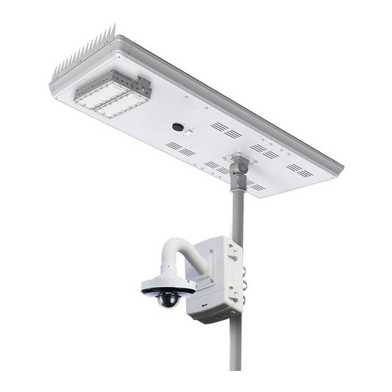
Solar ip camera system
Hide thumbs
Also See for SLR-B Series:
- Quick install manual (26 pages) ,
- Installation manual (24 pages) ,
- Quick install manual (24 pages)
Table of Contents
Advertisement
Quick Links
Advertisement
Table of Contents

Subscribe to Our Youtube Channel
Related Manuals for Vip-Vision SLR-B Series


Summary of Contents for Vip-Vision SLR-B Series
- Page 1 Solar IP Camera System SLR-B Series Quick Install Guide Version: VIPSLRB-Q121...
-
Page 2: Product Information
1. Product Information 1.1 Included Components Thank you for purchasing a VIP Vision Solar Surveillance System. Below is a list of what is included with the standard Solar Surveillance System. Please note that this can vary, depending on the customization options selected. Please refer to the included configuration sheet for specific product details. - Page 3 1.2 Optional Mounting Components Below are optional mounting components; please contact your supplier for more information. Unassembled Solar Base Assembled Solar Base SLR-POLBASE SLR-POLCONC 4.5m Hinged Galvanised Pole Includes 1 x Base, 4 x Mounting Bolts, 1 x Bolt Includes 1 x Base, 4 x Mounting Bolts, 1 x Bolt SLR-POL4.5H Template &...
- Page 4 1.3 Solar Panel Information 120W/180W Solar Panel with Motion-Sensing Street Light This solar panel system is fitted with undervoltage protection, which disconnects the load at approximately 10.8V (SLR-B120) or 21.6V (SLR-B180). If you are not receiving any voltage on the output wires, place the panel in direct sunlight for a minimum of one hour and re-test.
- Page 5 1.3 Solar Panel Information (continued) Solar Panel Assembly Diagram Lamp Arm Bird Spikes Accessories Component Solar panel LED light Microwave sensor Lamp arm Bird spikes Screws Safety rope T40 Torx...
-
Page 6: Camera Information
1.4 Camera Information The camera has been pre-installed with a 256GB microSD card and has been preconfigured to record at its maximum resolution. The username and password details for the camera can be found on the configuration sheet inside the junction box. The default username is admin. -
Page 7: Installation Prerequisites
2. Installation 2.1 Installation Prerequisites It is strongly recommend to have a minimum of two people performing installation of the solar panel, base, and pole. Required Install Tools: 5mm & 6mm Allen keys for junction box (included), T40 torx key for solar panel (included), 10mm Allen key, 20mm hole saw, battery drill, phillips screwdriver, flat head screwdriver, lifting equipment, padlock with key, large adjustable spanner. - Page 8 2.2 Installing the Optional Base (continued) Un-Assembled Base: 1. Locate a hard level surface to install the base, ensure that it is free from objects that will shade the solar panel, such as trees or buildings. 2. Install the reinforcing cage inside the base. Install a washer and nut on each threaded rod on the top side of the base, to secure the cage.
- Page 9 2.3 Installing the Optional Tilt Pole Warning: The tilt pole weighs approximately 100kg. Care must be taken to prevent injury when installing the pole. 1. Attach a lifting sling to the hinged part of the pole. 2. Unhinge the pole and position the pole base over the 4 threaded studs. Fig.
- Page 10 2.4 Mounting the Solar Panel to the Pole Caution: Solar panel must be placed so it is in direct sunlight all day. Any shading will greatly reduce the solar panel’s performance. 1. Drill an 20mm hole in the pole (minimum 15cm down from the top of the pole) on the same side that the camera will be mounted.
- Page 11 2.5 Adjusting the Solar Panel Angle To ensure your solar panel absorbs as much light as possible, it’s important to adjust the solar panel angle. For Australia and all locations in the southern hemisphere, the lower edge of the solar panel must point north. Locations in the northern hemisphere must have the lower edge of the panel pointing south.
- Page 12 2.6 Camera Mounting & Wiring 1. Open the junction box by loosening the 4 screws, and loosen the 2 screws (Fig. 2.6a), holding on the junction box mounting plate and pole bracket (Fig. 2.6b). 2. Mount the junction box mounting plate and pole bracket onto the pole using 3 included band clamps (Fig. 2.6c). Note: The 3 included band clamps are 65-89mm for poles 50-60mm in diameter.
- Page 13 2.7 Camera Mounting & Wiring (continued) 3. Reinstall the junction box to the junction box mounting plate, and securely fasten the 2 screws. Leave the junction box open. 4. If using a 4G solar kit, insert an active Micro SIM card into the SIM card slot in the modem. (Fig 2.7a) If using a Wi-Fi solar kit, mount the wireless antenna to the pole with the included mounting hardware, and attach the ethernet cable.
-
Page 14: Reconnect Battery
2.8 Reconnect Battery The Solar Light is shipped with the battery disconnected from the system. To activate the Solar Light, this battery must first be reconnected. To reconnect: 1. Remove the “Battery Disconnected” sticker. (Fig 2.8a) 2. Find the two cables labeled “Battery”. (Fig 2.8b) 3. -
Page 15: Connect Using Wifi
3. Wi-Fi (Applies to SLR-B120/180-4W Only) 3.1 Connect using WiFi This section covers how to set up the Access Point side of WiFi network for your WiFi Solar Surveillance Kit. Note: The station side of the wireless bridge should already be mounted under the solar panel. 1. - Page 16 4. Camera Remote Access 4.1 QR Code Remote Access Setup (4G) Internet access is required for remote access setup. 1. Install the free mobile application (DMSS) from the App Store for iOS or Play Store for Android. 2. Open the DMSS app you have installed on your device and select the “+” icon 3.
- Page 17 4.2 Adjusting Stream Settings You can choose between using Main or Sub stream when Live Viewing on the mobile application. (Fig. 3.2d) Main displays a higher quality stream but uses up more data and can take longer to load, while Sub consumes less data and bandwidth but has lower image quality.
- Page 18 5. Solar Panel, Sensor & Light Configuration 5.1 Solar Sensor Light Introduction This section covers how to set up the motion-activated 50W (SLR-B120) or 60W (SLR-B180) LED light on the solar panel. Our example will show you how to configure your solar panel & light with the remote control, showing you how to configure the light to activate after motion is detected at night.
- Page 19 5.2 Settings Detail Each Solar Light has default factory settings for light configuration and battery configuration. Below are the functions of each setting in the SysConfig menu and the solar system default settings . Before adjusting solar panel and light settings, familiarise yourself with the setting definitions below.
- Page 20 5.3 Activate LED Light Before activating the LED light system, the internal battery will require power. Place the solar panel outside and wait for it to charge in the sunlight for at least one hour before continuing. 1. Follow 4. Quick Solar Light Configuration to enable the solar light. 2.
- Page 21 5.5 Disable LED Light To disable the LED light system again, simply change the Drive Mode from Move Sensor to Time Ctrl. This will skip every Interval after the sun sets, so editing other values after this point is unnecessary. 5.6 Check Solar Panel On/Off Duration To check the solar panel’s current settings configuration, scroll to the SysConfig menu and press Enter.
-
Page 22: Troubleshooting
6. Troubleshooting Problem Troubleshooting • Ensure a SIM card is installed that is activated, and has data remaining on it. (4G Models) Cannot connect to camera remotely • Ensure solar panel is charged, and there is power to the modem and cam- •... - Page 23 Notes...
- Page 24 Version: VIPSLRB-Q121 Note: All products, designs and software here are subject to change without prior written notice.
Need help?
Do you have a question about the SLR-B Series and is the answer not in the manual?
Questions and answers