Sign In
Upload
Manuals
Brands
Vaisala Manuals
Accessories
FS11
Vaisala FS11 Manuals
Manuals and User Guides for Vaisala FS11. We have
1
Vaisala FS11 manual available for free PDF download: User Manual
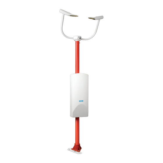
Vaisala FS11 User Manual (176 pages)
Visibility Sensor
Brand:
Vaisala
| Category:
Accessories
| Size: 18.98 MB
Table of Contents
Table of Contents
3
Chapter 1 General Information
11
About this Manual
11
Version Information
11
Related Manuals
11
Table 1 Manual Revisions
11
Table 2 Related Manuals
11
Documentation Conventions
12
Product-Related Safety Precautions
12
ESD Protection
14
Recycling
15
Regulatory Compliances
15
Trademarks
16
License Agreement
16
Warranty
16
Chapter 2 Product Overview
17
Description and Purpose
17
Mechanical Structure
18
Figure 1 FS11 System
18
Equipment Nomenclature
19
Table 3 FS11 Basic Nomenclature
19
Table 4 FS11 Options Nomenclature
20
Table 5 FS11 Recommended Accessories
20
Chapter 3 Installation
21
Organizing Installation
21
Location and Orientation
22
Figure 2 FS11 Recommended Location with Mast FSAM250/FSFM250
22
Unloading and Unpacking
24
Unpacking Procedure
24
Storage Information
24
Equipment Grounding and Lightning Protection
25
Figure 3 FS11 Equipment Grounding
26
Cable Selection
27
Line Power Cable
27
Figure 4 Junction Box
28
Communication Cable
29
Table 6 AC (Mains) Cable Selection
29
Installation Procedures
30
Foundation Construction
30
Figure 5 Casting Concrete Foundation
30
Mounting When Casting Pad
31
Figure 6 FS11 Foundation Construction
32
Figure 7 Mounting FS11 to Existing Surface
33
Mounting to Existing Surface
33
Assembling FS11
34
Figure 8 Mounting FS11 Mast Using Foundation Kit
34
Figure 9 Mounting FS11 Frangible Mast Grounding
35
Figure 10 Mounting FS11 Aluminum Mast Using Foundation Kit FS211296
36
Figure 11 Fixing Sensor Arm with allen Screws
37
Figure 12 Mounting Rear Panel of Radiation Shield
37
Figure 13 Tilting Aluminum and Frangible Pole Masts
38
Figure 14 Connecting Measurement Unit
39
Figure 15 Suspending Enclosure from Rear Panel
40
Figure 16 Threading Cable Connector with Cable Tie
40
Figure 17 Threading LM21 Cable
41
Figure 18 Mounting LM21
41
Figure 19 Mounting Interface Unit Enclosure
42
Figure 20 Sensor Arm Assembly
43
Inserting Battery for Optional FSB101
44
Figure 21 Mounting Radiation Shield
44
Figure 22 Backup Battery Without Cover Plate
45
Connecting Cables
46
Figure 23 Interface Unit Enclosure Cable
46
Power Cable
47
Figure 24 Cabling Principle
48
Communication Cable
49
Communication Options
50
Figure 25 Cable Grounding Instruction
50
Serial Communications Settings
50
Table 7 Communication Cable Lengths
50
Serial Transmission with
51
Figure 26 RS-232 Communication Option
52
Serial Multipoint Transmission with
52
Figure 27 RS-485 Communication Option
53
Figure 28 RS-485 Application
53
Figure 29 DXL421 Modem Wiring
54
Modem DXL421 (Optional)
54
Figure 30 Installing DXL421
56
Multipoint Modem Connection
57
Figure 31 Location of External Maintenance Line
58
Maintenance Terminal Connection
58
Background Luminance Options
59
Day/Night Photo Switch
59
LM21 Background Luminance Sensor
59
Figure 32 Wiring Day/Night Photo Switch
60
Obstruction Light Option
61
Figure 33 Obstruction Light Wiring
61
Startup
62
Figure 34 Switching on Unit
62
Initial Settings
63
Table 8 Default Communication Settings
63
Chapter 4 Operation
65
FS11 Commands
65
Entering and Exiting Command Mode
65
OPEN Command
66
CLOSE Command
67
Available Commands
67
Table 9 FS11 User Level Commands
67
Table 10 FS11 Advanced Level Commands
69
Command Completion
72
Terminal Line Number Adjustment
73
Command Polling
73
Message Formats
74
MESSAGE Command
75
Message 1, Fs11
75
Alarm Status Codes
76
Table 11 Alarm Status Codes
76
MESSAGE 2, FS11 with LM21
77
MESSAGE 3, Status Message
78
MESSAGE 4, Uncompensated Values
80
MESSAGE 5, Vaisala System Standard
81
FD12 Emulation
81
FD12 Message 2
82
FD12P Message 7
83
MITRAS Emulation
84
MITRAS Single Baseline
84
MITRAS Double Baseline
86
Message Sending Modes
88
Automatic Mode
88
ACK/NAK Confirmation
88
Polled Mode
90
Second Message
91
System Configuration
92
Default Factory Settings
92
Optional External Sensors
93
Day/Night Sensor
93
LM21 Background Luminance Sensor
93
Table 12 Default Factory Parameter Settings
93
Simulated Test Messages
94
Fixed Test Messages
94
Manual Simulation Message
95
Operating LM21 through Maintenance Port
97
Serial Communication Settings
97
Serial Transmission RS-232
97
Entering and Exiting Command Mode
98
CLOSE Command
98
OPEN Command
98
Available Commands
99
Table 13 LM21 User Level Commands
99
Table 14 LM21 Advanced Level Commands
100
Parameter Configuration
101
Default Settings for FS11 Use
102
LM21 Standard Initialization
102
Table 15 Default Settings for LM21 in FS11 Use
102
Chapter 5 Theory of Operation
103
Figure 35 FS11 Block Diagram
104
Hardware Description
105
Measurement Unit FSM102
105
Transmitter Unit FST102
105
Figure 36 FST102 Transmitter Block Diagram
106
Figure 37 Window Contamination Measurement Principle Inside Transmitter and Receiver FSM102
107
Receiver Unit FSR102
107
Figure 38 FSR102 Receiver Block Diagram
108
Controller Board FSC102
109
Interface Unit FSI102
109
AC (Mains) Power Supply
110
Communication Controller Board FSC202
110
Battery Backup
111
Frangible Mast
111
Software Description
112
Measuring Sequence
112
Visibility Measuring Principle
112
Calculations
113
Internal Monitoring
113
FS11 Status Messages
113
Event Messages
114
Table 16 Measurement Unit Event Messages
114
Table 17 Interface Unit Event Messages
115
Table 18 Background Luminance Detector Sensor Event Messages
116
Alarm Messages
119
Table 19 Error Messages
119
Table 20 Alarm Messages
119
Optical Contamination and Blocking Monitoring
120
Table 21 Warning Messages
120
Table 22 Indication Messages
120
Contamination Compensation
121
Signal Monitoring
122
Transmitter Intensity Stability
122
Heaters Operation
123
Power Supplies
123
Analog Interfaces
124
Figure 39 Location of Surface Temperature Probe
124
Communication Monitoring
125
Memory Tests and Program Operation
125
Background Luminance Sensor
126
Error Log
126
Chapter 6 Maintenance
127
Cleaning FSM102 Windows
127
FS11 Calibration
129
FSM102 Visibility Calibration
129
Figure 40 Installing Zero Plugs
130
FSM102 Calibration Check Procedure
130
Figure 41 Assembling and Attaching Calibrator
131
FSM102 Calibration Procedure
131
FSM102 Mechanical Alignment Check Procedure
132
Figure 42 Installing Mask Plates Onto Opaque Glass Plates
133
FSM102 Guided Calibration Procedure
133
Calibration Passed
136
Evaluating Results of Guided Calibration Procedure for Measurement Unit
136
Table 23 Successful Guided Calibration Procedure
137
Table 24 Guided Calibration Procedure, Calibration
138
Calibration Procedure Failed
139
Table 25 Guided Calibration Procedure, Scatter Signal Test Failed
139
Table 26 Guided Calibration Procedure, Zero Test Failed
140
Replacing FS11 Modules
141
Figure 43 Visibility Sensor Controller FSC102
142
Replacing FSC102
142
Figure 44 VS Bottom View, Central Compartment Cover
143
Figure 45 FSI102 Interface Unit
144
Replacing FSC202
144
Figure 46 Power and Battery Switch Locations
145
Figure 47 FSC202 Connectors and Cover Plate Screws
146
Figure 48 FSC202 Screws and Connectors
147
Replacing FSP103
148
Figure 49 FSP103 Parts
149
Figure 50 Visibility Sensor Transmitter and Receiver Control Cables
151
Replacing Transmitter Module FST102 and Receiver Module FSR102
151
Figure 51 End Plug Removal (Shown for Transmitter)
152
Figure 52 Module Retainer Removal (Shown for Transmitter)
152
Figure 53 Pushing Control Cable into Optics Head
153
Figure 54 Transmitter Resp. Receiver Module, Control
153
Figure 55 Pulling Control Cable out of Housing Tube
154
Figure 56 Transmitter/Receiver Module O-Ring
154
Figure 57 End Plug with O-Ring
155
Figure 58 FSP103 and FSC202 Sensor Cable Connections
157
Replacing/Installing Sensor Cables in FS11
157
Table 27 Wiring for LM21 Cable
158
Table 28 Wiring for FSM102 Cable
158
Replacing Fuses
159
Figure 59 Location of Fuses on FSP103 Board
159
Chapter 7 Troubleshooting
161
Error Messages
162
Errors
162
Table 29 Error Messages
162
Alarms
163
Table 30 Alarm Messages
163
Warnings
164
Table 31 Warning Messages
164
Indications
165
Table 32 Indication Messages
165
Miscellaneous Problems
166
Table 33 Miscellaneous Problems
166
Technical Support
168
Product Returns
168
Chapter 8 Technical Data
169
Specifications
169
Operational Specifications
169
Optical Specifications
169
Table 34 FS11 Operational Specifications
169
Table 35 FS11 General Optical Specifications
169
Electrical Specifications
170
Table 36 FS11 Transmitter Optical Specifications
170
Table 37 FS11 Receiver Optical Specifications
170
Table 38 FS11 Electrical Specifications
170
Mechanical Specifications
171
Environmental Specifications
171
Electromagnetic Compatibility
171
Table 39 FS11 Mechanical Specifications
171
Table 40 FS11 Environmental Specifications
171
Table 41 FS11 CE-Compliance
171
CRC16 Checksum
172
Index
173
Advertisement
Advertisement
Related Products
Vaisala FD12P
Vaisala FS11P
Vaisala FOC201
Vaisala FB15
Vaisala FC-11
Vaisala FB13
Vaisala TempCast FMP102
Vaisala TempCast FMP103
Vaisala DSC111
Vaisala DST111
Vaisala Categories
Transmitter
Measuring Instruments
Accessories
Test Equipment
Weather Station
More Vaisala Manuals
Login
Sign In
OR
Sign in with Facebook
Sign in with Google
Upload manual
Upload from disk
Upload from URL