Table of Contents
Advertisement
Quick Links
Advertisement
Table of Contents

Related Manuals for Advantech ARS-2110TX


Summary of Contents for Advantech ARS-2110TX
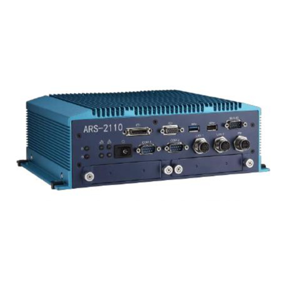
- Page 1 User Manual ARS-2110TX Railway Embedded Box PC...
- Page 2 Attention! Please note: This package contains a hard-copy user manual in Chinese for China CCC certification purposes, and there is an English user manual included as a PDF file on the CD. Please disregard the Chinese hard copy user manual if the product is not to be sold and/or installed in China. ARS-2110 User Manual...
- Page 3 The documentation and the software included with this product are copyrighted 2015 by Advantech Co., Ltd. All rights are reserved. Advantech Co., Ltd. reserves the right to make improvements in the products described in this manual at any time without notice.
- Page 4 Because of Advantech’s high quality-control standards and rigorous testing, most of our customers never need to use our repair service. If an Advantech product is defective, it will be repaired or replaced at no charge during the warranty period. For out-of- warranty repairs, you will be billed according to the cost of replacement materials, service time and freight.
- Page 5 Technical Support and Assistance 1. Visit the Advantech web site at www.advantech.com/support where you can find the latest information about the product. 2. Contact your distributor, sales representative, or Advantech's customer service center for technical support if you need additional assistance. Please have the following information ready before you call: –...
- Page 6 17. The sound pressure level at the operator's position according to IEC 704-1:1982 is no more than 70 dB (A). 18. RESTRICTED ACCESS AREA: The equipment should only be installed in a Restricted Access Area. 19. DISCLAIMER: This set of instructions is given according to IEC 704-1. Advantech disclaims all ARS-2110 User Manual...
- Page 7 20. This product is intended to be supplied by a Listed DC power source, rate 24Vdc, 4.2A; 72Vdc, 2.1A; 110Vdc, 0.9A minimum and Tma 60 degree C, if need further assistance, please contact Advantech for further information. ARS-2110 User Manual...
-
Page 8: Table Of Contents
Contents Chapter 1 General Introduction ........1 Introduction ……………………………………………………………… 2 Product Features................2 1.2.1 General .................. 2 1.2.2 Display .................. 2 1.2.3 Power Consumption .............. 2 Hardware Specifications..............2 1.3.1 Block Diagram ............... 3 Figure 1.1 ARS-2110 Block diagram……..…………....3 Mechanical Specifications..............4 1.4.1 Dimensions ................ - Page 9 Figure 2.3 RTC Connector……….………..……….… 8 Table 2.2 RTC Connector (CN1)….………..……….. 8 2.2.3.2 Debug Port (CN3)……….…………..………………... 8 Figure 2.4 Debug Port…………..….……………..….. 8 Table 2.3 Debug Port (CN3)….……………………… 9 2.2.3.3 DVI-D Inverter Connector (CN6)….…………………. 9 Figure 2.5 DVI Inverter Connector………………… 9 Table 2.4 DVI Inverter Connector……………….… 9 2.2.3.4 ITE Debug Port (CN10)….....………………...…...
- Page 10 Table 2.16 USB 2.0 Header (USB1)………..……….16 2.2.3.15 LAN Header (LAN1 / 2)………..……………….. 17 Figure 2.17 LAN Header….………………………..17 Table 2.17 LAN Header (LAN1 / 2)………..………. 17 2.2.3.16 LED Header (LED1)………..…………………….17 Figure 2.18 LAN Header….………………………..17 Table 2.18 LAN Header (LAN1 / 2)………..………...17 2.2.3.17 USB2.0 Header (USB2)………………………………17 Figure 2.19 USB2.0 Header (USB2)……………..
- Page 11 2.3.2 Rear External I/O Connectors…………………………...…..…. 22 2.3.2.1 Power Input Connector……………………………… 22 Figure 2.30 M12 Power Input Connector……..…… 22 Table 2.28 Power Input Connector………..……….. 22 Figure 2.31 Ground Screw……..…………………… 23 Installation……………………………………………………………….. 24 2.4.1 GSM-R and 4G SIM Card Installation……………………….. 24 2.4.2 mSATA Installation……..………………………………..…. 25 Chapter 3 BIOS Settings ..........
- Page 12 3.3.11 USB Configuration…………...……………………………………..….. 42 Figure 3.18 USB Configuration………..…………………………….. 42 3.3.12 Security Configuration……………………...………………………….. 43 Figure 3.19 Security Configuration……..…………………………….. 43 3.3.13 Info Report Configuration……………………..…………..……………. 44 Figure 3.20 Info Report Configuration……..…………………………. 44 Chipset.………………………………………………………….……………….. 45 Figure 3.21 Chipset Setup…..…………………………………………………. 45 3.4.1 North Bridge…………………………………………………………….. 45 Figure 3.22 North Bridge……………………...………………………..
-
Page 13: General Introduction
Chapter General Information This chapter gives background information on the ARS-2110 Computing Box. Sections include: Introduction General Specifications Dimensions... -
Page 14: Introduction
Introduction The ARS-2110 is a dedicated box computer for railway. ARS-2110 combines various I/O connectors which can be connected to devices such as LED displays (PIDS, Passenger Information Display Systems). Dual display / dual audio interfaces supporting different resolutions are able to deliver various applications to diverse displays. -
Page 15: Block Diagram
High Definition Audio (HD), SPK, Line out, Mic-in Storage: 1 × mSATA Expansion Interface: Support WWAN with SIM holder, GSM-R with SIM holder and WLAN Software API: Advantech iManager and SUSIAccess 1.3.1 Block Diagram Figure 1.1 ARS-2110 Block Diagram Mechanical Specifications 1.4.1 Dimensions 270[10.62] x 175[6.69] x 90[3.54] (Unit: mm [Inch]) -
Page 16: Weight
Figure 1.2 ARS-2110 Mechanical dimension drawing 1.4.2 Weight 4 kg (8.8lb) Power Requirement 1.5.1 System Power Power Input: 24Vdc@ 4.2A ARS-2110 User Manual... -
Page 17: Rtc Battery
72Vdc@ 2.1A 110Vdc@ 0.9A 1.5.2 RTC Battery Lithium 3V / 210 mAh Environment Specification 1.6.1 Operating Temperature With Industrial Grade SSD: -40 ~ 70 ℃ (-13 ~158 ℉), with air flow. Speed=0.7 m/sec Certified Safety Temperature: 60℃ (140℉) ... -
Page 18: H/W Installation
Chapter H/W Installation This chapter introduces external IO and the installation of ARS- 2110 hardware. -
Page 19: Introduction
Introduction The following sections show the internal connectors and the external connectors pin assignment for application. Internal Connectors 2.2.1 Connector List Table 2.1: Connector List of Main Board RTC Connector WLAN1_1 WLAN Module Connector Debug Port WWAN1_1 WWAN Module Connector GPS1 GPS Module Connector WWAN2... -
Page 20: Connector Pin Assignment
Figure 2.2 Internal Connectors of MB Bottom Side 2.2.3 Connector Pin Assignment 2.2.3.1 RTC Connector (CN1) Figure 2.3 RTC Connector Table 2.2 RTC Connector (CN1) Signal +VBAT 2.2.3.2 Debug Port (CN3) Figure 2.4 Debug Port Table 2.3 Debug Port (CN3) Signal Signal CLK33M_DEBUG... -
Page 21: Dvi-D Inverter Connector (Cn6)
DEBUG_PLTRST#17 4 LPC_AD0 LPC_FRAME# +V3P3S LPC_AD3 LPC_AD2 2.2.3.3 DVI-D Connector Figure 2.5 DVI Connector Table 2.4 DVI-D Connector Signal Signal TMDS Data 2- TMDS data 2+ DDC clock DDC data TMDS Data 1- TMDS Data 1+ Hot plug detect TMDS Data 0- TMDS Data 0+ TMDS clock+ TMDS clock-... -
Page 22: Com Header (Cn11 / 12)
EC_KSI1 EC_KSI0 EC_KSO15 EC_KSO14 EC_KSO13 EC_KSO12 EC_KSO11 EC_KSO10 EC_KSO9 EC_KSO8 EC_KSO7 EC_KSO6 EC_KSO5 EC_KSO4 EC_KSO3 EC_KSO2 EC_KSO1 EC_KSO0 2.2.3.5 COM Header (CN11 / CN12) Figure 2.7 COM Header (CN11 / CN12) Table 2.6 COM Header (CN11 / CN12) Signal Signal DCD# DTR# DSR#... -
Page 23: Msata Module Connector (Sata1_1)
Table 2.8 Reset Button Connector (CN16) Signal Signal KBRST# 2.2.3.8 mSATA Module Connector (SATA1_1) Figure 2.10 mSATA Module Connector Table 2.9 mSATA Module Connector Signal Signal +V3.3 +V3.3 PLTRST# +V1.5S USB_D- USB_D+ +V3.3 +V3.3 ARS-2110 User Manual... -
Page 24: Wlan Module Connector (Wlan1_1)
+V1.5 LED_SATA# +V3.3 2.2.3.9 WLAN Module Connector (WLAN1_1) Figure 2.11 WLAN Module Connector Table 2.10 WLAN Module Connector (WLAN1_1) Signal Signal +V3.3 +V3.3 CLKREQ# PCIE_CLKN2 PCIE_CLKP2 +V3.3 PLTRST# PCIE_ RX7- PCIE_ RX7+ +V1.5 PCIE_ TX7- PCIE_ TX7+ USB_D- USB_D+ +V3.3 +V3.3 LED_WLAN# +V1.5... -
Page 25: Wwan Module Connector (Wwan1_1)
+V3.3 2.2.3.10 WWAN Module Connector (WWAN1_1) Figure 2.12 WWAN Module Connector Table 2.11 WWAN Module Connector (WWAN1_1) Signal Signal WAKE_WWAN# +V3.3 +VUM_PWR UM_DATA UM_CLK UM_RESET GPS_RESET# +V3.3 USB_D- USB_D+ +V3.3 +V3.3 LED_WAN# +V3.3 ARS-2110 User Manual... -
Page 26: Gsm-R Module Connector (Wwan2)
2.2.3.11 GSM-R Module Connector (WWAN2) Figure 2.13 GSM-R Module Connector Table 2.12 GSM-R Module Connector (WWAN2) Signal Signal USIM_CLK +VUSIM USIM_DATA USIM_RST USIM_PRSNT GND_USIM Flash RXD2_RF RXD1_RF TXD2_RF TXD1_RF +V_WWAN +V_WWAN +V_WWAN +V_WWAN +V_WWAN +VINT_GPRS RI1#_RF DSR1#_RF RTS1#_RF DTR1#_RF RTS2#_RF CTS1#_RF CTS2#_RF DCD1#_RF... -
Page 27: Wwan / Gsm-R Sim Slot (Sim1 / Sim2)
Figure 2.14 WWAN / GSM-R SIM Slot Table 2.13 WLAN SIM Slot (SIM1) Signal Signal +VUIM_PWR UIM_RESET UIM_CLK +VUIM_VPP UIM_DATA Table 2.14 GSM-R SIM Slot (SIM2) Signal Signal +VSIM SIM_RST SIM_CLK GND_USIM SIM_DATA ARS-2110 User Manual... -
Page 28: Gps Module Connector (Gps1)
2.2.3.13 GPS Module Connector (GPS1) Figure 2.15 GPS Module Connector (GPS1) Table 2.15 GPS Module Connector (GPS1) Signal Signal +V5S +V5S USB_D- USB_D+ SPEED+ GND_ISO UART4_TXD FWD+ UART4_RXD GND_ISO LED_GPS# USB2_SSTX- USB2_SSRX+ 2.2.3.14 USB2.0 Header (USB1) Figure 2.16 USB2.0 Header (USB1) Table 2.16 USB2.0 Header (USB1) Signal Signal... -
Page 29: Lan Header (Lan1 / 2)
2.2.3.15 LAN Header (LAN1 / LAN2) Figure 2.17 LAN Header Table 2.17 LAN Header (LAN1 / LAN2) Signal Signal LAN_MDI3- LAN_MDI3+ LAN_MDI2- LAN_MDI2+ LAN_MDI1- LAN_MDI1+ LAN_MDI0- LAN_MDI0+ 2.2.3.16 LED Header (LED1) Figure 2.18 LED Header Table 2.18 LED Connector (LED1) Signal Signal LAN2_a_LINK100#... -
Page 30: External Connectors
Table 2.19 USB2.0 Header (USB2) Signal Signal +5V_USB USB- USB+ External Connectors 2.3.1 Front External I/O Connectors Figure 2.20 ARS-2110 IO View 2.3.1.1 LED Indicators There are six LEDs on ARS-2110 front metal surface plate for system status indication: PWR LED stands for power status, HDD LED stands for HDD status, and LAN LED stands for LAN speed and active status. -
Page 31: Power On/Off Button
Figure 2.21 LED Indicators Table 2.20 LAN LED Indicator 10/100 Orange 1000 Green 2.3.1.2 Power ON/OFF Button ARS-2110 comes with a Power ON/OFF button which supports dual functions of Soft Power -ON/OFF (DOS: Instant off, Windows: 4 Seconds Delay). Figure 2.21 Power Button 2.3.1.3 VGA Connector The ARS-2110 provides a high resolution VGA interface connected by a D-sub... -
Page 32: Com Connector
which offer RS-232/422/485 serial communication interface. The default setting is RS-232 and RS-422/485 can be selected in BIOS. The BIOS setting of RS-232/422/485 can be found in Chapter 3. Figure 2.24 COM Connector Table 2.22 COM connector RS-232 RS-422 RS-485 DCD# Data - Data +... -
Page 33: M12 A-Coded Lan Connector
swapping with up to 127 external devices. Figure 2.26 USB 2.0 Connector Table 2.24 USB 2.0 Connector Signal Signal USB_data- USB_data+ 2.3.1.7 M12 A-Coded LAN Connector Figure 2.27 M12 LAN Connector Table 2.25 LAN Connector of M12 A-Coded Signal Signal MDI2+ MDI3+ MDI3-... -
Page 34: Rear External I/O Connectors
Data + 2.3.1.9 Multi IO Connectors Figure 2.29 Multi IO Connector Table 2.27 Multi IO Connector Signal Signal Line L GND_AUD FWD+ Line R APORT_L1 GND_AUD GND_ISO GND_AUD APORT_R1 MIC_L MIC_R SPEED+ 2.3.2 Rear External I/O Connectors 2.3.2.1 Power Input Connector ARS-2110 comes with a 4-pins M12 A-coded connector which is for VDC external power input. - Page 35 Figure 2.31 Ground Screw Please make the earth lead well locked at the ground screw. Connection for DC Power Source: Attention: Only trained service personnel are authorized to install and remove the 24,72,110 volt DC power supply, and make the connections to and disconnections from the 24,72,110 volt DC power source.
-
Page 36: Installation
Installation 2.4.1 GSM-R and 4G SIM Card Installation Unscrew the four screws at the top cover. Unscrew the four screws at the right and left side of top cover. ARS-2110 User Manual... -
Page 37: Msata Installation
Remove the top cover. Install the 4G SIM card into SIM1 and GSM-R SIM card into SIM2. Recover the top cover and screws. 2.4.2 mSATA Installation Unscrew the four screws at the bottom side. ARS-2110 User Manual... - Page 38 ARS-2110 User Manual...
- Page 39 Unscrew five screws at the rear side. Remove the bottom cover. Please make sure the step (A) is processed horizontally in order not to damage the special connector inside. ARS-2110 User Manual...
- Page 40 Install mSATA module into SATA1_1 connector. Recover bottom cover and screws. ARS-2110 User Manual...
-
Page 41: Chapter 3 Bios Settings
Chapter BIOS Settings... -
Page 42: Entering Setup
AMIBIOS has been integrated into many motherboards for over a decade. With the AMIBIOS Setup program, users can modify BIOS settings and control various system features. This chapter describes the basic navigation of the ARS-2110 BIOS setup screen. Figure 3.1 Setup Program Initial Screens AMI's BIOS ROM has a built-in Setup program that allows users to modify the basic system configuration. -
Page 43: System Time / System Date
Figure 3.2 Main Setup Screens The Main BIOS setup screen has two main frames. The left frame displays all the options that can be configured. Grayed-out options cannot be configured; options in blue can. The right frame displays the key legend. Above the key legend is an area reserved for a text message. When an option is selected in the left frame, it is highlighted in white. -
Page 44: Acpi Settings
Figure 3.3 Advanced BIOS Features Setup Screen 3.3.1 ACPI Settings Figure 3.4 ACPI Settings Enable ACPI Auto Configuration This item allows users to enable or disable BIOS ACPI auto configuration. Lock Legacy Resources This item allows users to lock legacy device resources. 3.3.2 Intel®... -
Page 45: Intel® Smart Connect Technology
Figure 3.5 Intel® Smart Connect Technology ISCT Support This item allows user to enable or disable ISCT Support. 3.3.3 Serial Port Configuration Figure 3.6 Intel® Super IO Configuration ARS-2110 User Manual... - Page 46 Figure 3.7 Serial Port 1 Configuration Figure 3.8 Serial Port 2 Configuration RS Mode This item allows users to set COM port interface into RS-232, RS-422 and RS-485. ARS-2110 User Manual...
-
Page 47: S5 Rtc Wake Settings
3.3.4 S5 RTC Wake Settings Figure 3.9 S5 RTC Wake Settings Wake system from S5 This item allows user to enable or disable system wake on alarm event. 3.3.5 CPU Configuration Figure 3.10 CPU Configuration Intel Virtualization Technology This item allows users to enable or disable the Intel virtualization technology. ARS-2110 User Manual... -
Page 48: Ppm Configuration
3.3.6 PPM Configuration Figure 3.11 PPM Configuration CPU C State Report This item allows users to enable or disable CPU C-state report to OS. Max CPU C-state This item allows users to control max C state that the processor will support. SOix This item allows users to enable or disable CPU SOix state. -
Page 49: Ide Configuration
3.3.7 IDE Configuration Figure 3.12 IDE Configuration Serial-ATA (SATA) This item allows users to enable or disable Serial-ATA. SATA Test Mode This item allows users to enable or disable SATA test mode. SATA Speed Support This item allows users to select the SATA speed support with Gen1 or Gen2. SATA ODD Port This item allows users to select SATA ODD port. -
Page 50: Miscellaneous Configuration
3.3.8 Miscellaneous Configuration Figure 3.13 Miscellaneous Configuration High Precision Timer This item allows users to enable or disable high precision event timer. PCI Express Dynamic C This item allows users to enable or disable PCIE dynamic clock gating. OS Selection This item allows users to select the OS which is supported. - Page 51 Figure 3.15 PCI Express Settings Relaxed Ordering This item allows users to enable or disable PCIE device relaxed ordering. Extended Tag This item allows users to enable or disable using 8-bit tag field as a requester. No Snoop This item allows users to enable or disable PCI device no snoop option. Maximum Payload This item allows users to set maximum payload of PCIE device or allow system BIOS to select the value.
- Page 52 This item allows users to define the number of microseconds which software will wait before polling ‘Link Training’ bit in link status register. Unpopulated Links This item allows users to keep unpopulated PCIE links on or disable to save power. Restore PCIE Register This item allows users to enable or disable restoring PCIE device configurations on S3 resume.
-
Page 53: Csm Configuration
Target Link Speed This item allows users to set an upper limit on operational speed. Clock Power Management This item allows users to enable or disable the device to use CLKREQ# signal for power management of Link clock in accordance to protocol defined. Compliance SOS This item allows users to enable or disable forcing LTSSM to send SKP Ordered Sets between sequences when sending Compliance Pattern or Modified Compliance Pattern. -
Page 54: Usb Configuration
This item allows user to control Legacy/UEFI ROM’s priority. Network This item allows user to control the execution of UEFI and Legacy PXE OpROM. Storage This item allows user to control the execution of UEFI and Legacy Storage OpROM. Video This item allows user to control the execution of UEFI and Legacy video OpROM. -
Page 55: Security Configuration
This item allows users to limit the maximum time before the device properly reports itself to the host controller. 3.3.12 Security Configuration Figure 3.19 Security Configuration TXE EOP Message This item allows users to enable or disable sending EOP message before entering OS. TXE Unconfiguration Perform This item allows users to revert TXE settings to factory defaults. -
Page 56: Info Report Configuration
3.3.13 Info Report Configuration Figure 3.20 Info Report Configuration Post Report This item allows users to enable or disable post report support. Delay Time This item allows users to limit the post report waiting time period. Info Error Message This item allows users to enable or disable info error message support. Summary Screen This item allows users to enable or disable summary screen support. -
Page 57: Chipset
Chipset Select the Chipset tab from the ARS-2110 setup screen to enter the Chipset BIOS Setup screen. You can display a Chipset BIOS Setup option by highlighting it using the <Arrow> keys. All Plug and Play BIOS Setup options are described in this section. The Plug and Play BIOS Setup screen is shown below. - Page 58 Max TOLUD This item allows users to limit the maximum value of TOLUD. Figure 3.23 Intel IGD Configuration GOP Driver This item allows users to enable or disable GOP driver loading VBIOS. Integrated Graphics Device This item allows users to enable or disable integrated graphics device when selected as primary video adaptor.
- Page 59 GTT Size This item allows users to set GTT size. IGD Thermal This item allows users to enable or disable IGD thermal. Spread Spectrum Clock This item allows users to enable or disable spread spectrum clock. ISP Enable/Disable This item allows users to enable or disable ISP PCI device selection. ISP PCI Device Selection This item allows users to select the ISP PCI device value for different OS.
-
Page 60: South Bridge
3.4.2 South Bridge Figure 3.25 South Bridge High Precision Timer This item allows users to enable or disable the high precision event timer. Serial IRQ Mode This item allows users to configure serial IRQ mode. Global SMI Lock This item allows users to enable or disable SMI lock. BIOS Read/Write Protection This item allows users to enable or disable BIOS SPI region read/write protection. - Page 61 This item allows users to enable or disable control detection of the Azalia device. Azalia VCi Enable This item allows users to enable or disable virtual channel 1 of audio controller. Azalia PME Enable This item allows users to enable or disable power management capability of audio controller. Figure 3.27 USB Configuration XHCI Mode This item allows users to enable or disable XHCI mode.
-
Page 62: Security Setup
Security Setup Figure 3.28 Password Configuration Select Security Setup from the ARS-2110 Setup main BIOS setup menu. All Security Setup options, such as password protection is described in this section. To access the sub menu for the following items, select the item and press <Enter>: Change Administrator / User Password: Select this option and press <ENTER>... -
Page 63: Boot Settings
Boot Settings Figure 3.29 Boot Setup Utility Setup Prompt Timeout This item allows users to select the number of seconds to wait for setup activation key. Bootup NumLock State Select the Power-on state for Numlock. Quiet Boot If this option is set to Disabled, the BIOS displays normal POST messages. If Enabled, an OEM Logo is shown instead of POST messages. -
Page 64: Save & Exit
Save & Exit Figure 3.30 Save & Exit Save Changes and Exit When users have completed system configuration, select this option to save changes, exit BIOS setup menu and reboot the computer if necessary to take effect all system configuration parameters. - Page 65 Save User Defaults When users have completed system configuration, select this option to save changes as user defaults without exit BIOS setup menu. Restore User Defaults The users can select this option to restore user defaults. ARS-2110 User Manual...
-
Page 66: Appendix A Watchdog Timer Sample Code
Appendix Watchdog Timer Sample Code... - Page 67 EC Watchdog Timer Sample Code EC_Command_Port = 0x29Ah EC_Data_Port = 0x299h Write EC HW ram = 0x89 Watch dog event flag = 0x57 Watchdog reset delay time = 0x5E Reset event = 0x04 Start WDT function = 0x28 ==================================================== .model small .486p .stack 256 .data...
Need help?
Do you have a question about the ARS-2110TX and is the answer not in the manual?
Questions and answers