Table of Contents
Advertisement
Quick Links
Advertisement
Chapters
Table of Contents
Troubleshooting

Related Manuals for Siemens SIMPRO-100


Summary of Contents for Siemens SIMPRO-100
- Page 1 SIMPRO-100 Motor Protection Relay Instruction Manual Document No. PRIM-2400C...
- Page 2 The sales contract contains the entire obligation of Siemens. The warranty contained in the contract between parties is the sole warranty of Siemens. Any statements contained herein do not create new warranties or modify the existing warranty.
-
Page 3: Table Of Contents
RTD Connections at the SIMPRO-100-RTD Module........38... - Page 4 RTD Alarm & Trip Temperatures ..........60 Voltage-Based Protection (Relay Models SIMPRO-100-R or N-V) ......63 4.6.1...
- Page 5 Contents SIMPRO-100 Front-Panel Operation ..........75 Front-Panel Layout .
- Page 6 Contents SIMPRO-100 6.8.24 MSR (Level 1 or 2) ............93 6.8.25 MST (Level 1 or 2) .
- Page 7 Contents SIMPRO-100 Power Measurement Conventions ............113 Load Profiling .
- Page 8 Contents SIMPRO-100 10.3 Troubleshooting Procedure ............129 10.3.1 Relay Enabled Front-Panel LED Dark .
- Page 9 D.5.2 SIMPRO-100 Relay Command Response Contents........198 CSTATUS Command ..............199...
- Page 10 SIMPRO-100 Relay Settings Sheets........
- Page 11 Contents SIMPRO-100 Output Configuration ..............224 F.3.1...
- Page 12 Contents SIMPRO-100 PRIM-2400C...
-
Page 13: List Of Figures
Figure 2.5 SIMPRO-100 Relay Left- and Right-Side Panel Drawings ......29 Figure 2.6 Example AC Wiring Diagram, Four-Wire Wye Voltages and Ground CT . - Page 14 Contents SIMPRO-100 Figure 5.13 Main Menu: Set Relay Function ..........80 Figure 5.14...
- Page 15 Contents SIMPRO-100 Figure B.4 Control Equation Variable Timer Logic ..........146 Figure B.5...
- Page 16 Contents SIMPRO-100 PRIM-2400C...
-
Page 17: List Of Tables
SIMPRO-100 Relay Order Number Creation Table ........22... - Page 18 SIMPRO-100 Serial Port Command Summary ........
- Page 19 Table 9.1 SIMPRO-100 Relay Front-Panel Target LED Definitions ......117 Table 9.2 Event Commands .
- Page 20 Contents SIMPRO-100 Table B.4 Remote Control Switch............151 Table C.1...
-
Page 21: Introduction & Specifications
Describes the relay commissioning select, install, set, test, operate, and maintain any procedure; provides protection element test SIMPRO-100 Relay. You probably will not need to procedures. review the whole book to perform the specific tasks that are your responsibility. The following is Chapter 8, "Metering &... -
Page 22: Typographic Conventions
SIMPRO-100 Relay. Table 1.1 SIMPRO-100 Relay Models For more information on creating a SIMPRO-100 Relay order number, Section 1.7, page 22. When differences between the SIMPRO-100 Relay models in Table 1.1 are explained, model numbers are referenced for clarity. -
Page 23: Simpro-100 Relay Applications
Introduction & Specifications SIMPRO-100 SIMPRO-100 Relay SIMPRO-100 Relay Applications Protection Features The SIMPRO-100 Relay offers a full range of elements for motor protection, including: • Flexible motor thermal element (49) that provides integrated protection for locked rotor, running overload, unbalanced current/ negative-sequence current heating, and repeated or frequent starts. -
Page 24: Simpro-100 Relay Monitoring & Reporting Features
Monitoring & To obtain a quotation or place an order for a Reporting Features SIMPRO-100 Relay, it is helpful to have a relay part number. The following information helps you create a part number for the SIMPRO-100 Relay In addition to the protection functions outlined... -
Page 25: Communication Cables
1.7.2 Communication Cables Figure 1.2 shows the serial number label for the SIMPRO-100 Relay. The label is affixed to the top Remember to order required serial of the relay chassis. From the top of the label, the communication cables with the relay. - Page 26 Introduction & Specifications SIMPRO-100 Motor Thermal Model Starts Per Hour, Time Between Starts Locked Rotor Time: 1.0 – 240.0 s Max. Starts/Hour: 1 – 15 starts Locked Rotor Current: 2.5 – 16.0 • I Min. Time Bet. Starts: 1 – 150 minutes Service Factor: 1.0 –...
-
Page 27: Optional Features & Functions
Introduction & Specifications SIMPRO-100 Interrupt: 8 A Resistive @ 250 Vac Underpower Element Alarm and Trip Levels 0.75 A, L/R = 40 ms @ 24 Vdc Setting Range: 30 – 2000 W, 5 A tap 0.50 A, L/R = 40 ms @ 48 Vdc 6 –... -
Page 28: Reporting Functions
Introduction & Specifications SIMPRO-100 1.9.3 Reporting Functions Impulse: IEC 255-5 : 1977, 5 kV 0.5 j Electrostatic Event Summaries/Event Reports Discharge: IEC 801-2 : 1991, Level 4 IEC 255-22-2 : 1989, Level 4 14 Latest Summaries and 15-Cycle Oscillographic Records... -
Page 29: Installation
Panel Cut & Drill Plans Figure 2.1, page 27 shows the mechanical dimensions of the SIMPRO-100 Relay. Figure 2.2, page 28 shows the dimensions of the panel cutout required to mount the relay. Guard against accidental contact with relay rear... -
Page 30: Relay Mounting
Weather Gasket Relay 6-32 Self-Locking Nut (4 places) Figure 2.2 SIMPRO-100 Relay Cut and Drill Dimensions Relay Mounting Mount the relay in the prepared panel cutout using the four mounting studs and the locknuts Figure 2.3 SIMPRO-100 Relay Panel Mounting provided. -
Page 31: Figure 2.4 Simpro-100 Relay Rear Panel
Installation SIMPRO-100 Figure 2.4 SIMPRO-100 Relay Rear Panel Figure 2.5 SIMPRO-100 Relay Left- and Right-Side Panel Drawings PRIM-2400C... -
Page 32: Figure 2.6 Example Ac Wiring Diagram, Four-Wire Wye Voltages And Ground Ct
Installation SIMPRO-100 Figure 2.6 Example AC Wiring Diagram, Four-Wire Wye Voltages and Ground CT Figure 2.7 Example AC Wiring Diagram, Open-Delta Voltages and Residual IN Connection PRIM-2400C... -
Page 33: Relay Connections
Installation SIMPRO-100 Relay Connections 2.4.1 Input Power Connections Figure 2.8 Example AC Voltage Wiring Diagram, The SIMPRO-100 Relay power supply has a Single Phase-to-Phase Voltage broad operating range that can accept ac or dc inputs. Power Supply Operating Range: •... -
Page 34: Current Transformer Inputs
Inputs connect the motor to the source. As Figure 2.10 shows, using unshielded cable requires that the The SIMPRO-100 Relay is equipped with four CT be placed between the neutral connection to current transformer inputs: IA, IB, IC, and IN. -
Page 35: Figure 2.11 Contact Output Factory Default Wiring Diagram
Installation SIMPRO-100 operate in fail-safe mode, the relay holds the contact in an energized position continuously, then deenergizes the contact to trip. The contact is also deenergized if the relay input power is removed. The connections shown in Figure 2.11, page 33 are suitable for use with a motor contactor when trip fail-safe operation is desired. -
Page 36: Figure 2.12 Trip Contact Fail-Safe, Nonfail-Safe Wiring Options
RTD Bias alarm picks up, if RTD leads short or open, or if the relay loses communication with the SIMPRO-100-RTD Module. This output is inactive if the relay is not equipped with RTD inputs. PRIM-2400C... -
Page 37: Contact Inputs
2.4.6 Contact Inputs Shorting the IN4 input makes password entry unnecessary; this is The SIMPRO-100 Relay is equipped with six useful if the Access Level 2 password internally wetted contact inputs. The relay is lost. supplies 28 Vdc wetting voltage for each input so you only need to connect a dry contact, switch, or •... -
Page 38: Internal Rtd Connections (Relay Models Simpro-100-R-V Or N)
2.4.8 Internal RTD Connections (Relay Models SIMPRO-100–R–V or N) The SIMPRO-100 Relay is available with 11 optional internal RTD inputs. When the relay is equipped with internal RTD inputs, you can enter relay settings that define the type, location, trip, and alarm temperatures for each input individually. -
Page 39: Ac Voltage Connections (Relay Models Simpro-100-R Or N-V)
(Relay Models the A-N or A-B voltage is connected to the SIMPRO-100-R or N-V) relay. The SIMPRO-100 Relay is available with optional 2.4.10 EIA-232 Communication voltage inputs and associated metering, protection, and reporting functions. When your... -
Page 40: Simpro-100-Rtd Module
SIMPRO-100-RTD 2.5.2 Fiber-Optic Connection to SIMPRO-100-RTD Module Module Connect the SIMPRO-100-RTD Module Fiber-Optic TX port to the SIMPRO-100 Relay 2.5.1 RTD Connections at the Fiber-Optic RX port using a Siemens Fiber-Optic SIMPRO-100-RTD Module Cable SIM-RTD-XXX (xxx = number meters). The... -
Page 41: Simpro-Pc Software
SIMPRO-100 Relay. This software following steps: package allows you to do the following: 1. With your PC turned on and all applications • Create settings for one or more SIMPRO-100 closed, load the SIMPRO-PC software Relays. CD-ROM into your CD-ROM drive. •... - Page 42 SIMPRO-PC Software SIMPRO-100 PRIM-2400C...
-
Page 43: Settings Calculation
Lists settings associated with the optional internal RTD inputs (Relay Models The SIMPRO-100 Relay protection settings are SIMPRO-100-R-V or N) or if the relay will be divided into two major categories. The first connected to the External RTD Module category, described in this section, includes (SIMPRO-100-RTD). -
Page 44: Application Data
Type and location of resistance temperature It is quicker and easier for you to calculate devices (RTDs), if used. settings for the SIMPRO-100 Relay if you collect the following information before you begin: • Expected fault current magnitudes for motor or cable ground and three-phase faults. -
Page 45: General Data
Consider an application where the phase CT ratios are 600:5. 4.3.1 Identifier Settings Set CTR = 600/5 = 120 All models of the SIMPRO-100 Relay have the following identifier settings: Set ITAP = 5 A Select phase current transformers for your Setting Name =... -
Page 46: Voltage Transformer (Vt) Configuration Settings (Relay Models Simpro-100-R-V Or N)
Configuration Settings • Power Elements (Relay Models When you use one voltage, the relay SIMPRO-100-R-V or N) assumes that the system voltages are balanced in both magnitude and phase angle to calculate apparent, real, and reactive Setting Setting Name = Setting Prompt power and the power factor. -
Page 47: Basic Motor Protection
Meter Values\Thermal & RTD Data function or the serial port METER T command. 4.4.1 Thermal Model Element 4.4.1.1 Thermal Element RATING The SIMPRO-100 Relay motor thermal element Setting Method provides integrated protection for all of the following motor operating conditions: Setting Setting Setting Name = •... -
Page 48: Table 4.7 Thermal Element Configuration Settings, Setting Method = Generic
1.00, except in an emergency to A 4160 V, 600 HP motor is to be protected allow a start with a longer than normal using the SIMPRO-100 Relay Thermal accelerating time. Element Rating Method. The motor data sheet includes the following information. - Page 49 10 trip time at six times full load ratios are selected for the application. The current is 25 seconds. Table 4.8, page 49 and SIMPRO-100 Relay settings for the Table 4.9, page 49 show the cold motor thermal application are shown below.
-
Page 50: Figure 4.2 Generic Thermal Limit Curves, Cold Motor
Settings Calculation SIMPRO-100 Figure 4.2 Generic Thermal Limit Curves, Cold Motor PRIM-2400C... -
Page 51: Table 4.8 Generic Thermal Limit Curve Tripping Times From Reset Versus Multiples Of Full Load Amps, Curves 1 - 10 (Thermal Limit Times In Seconds)
Settings Calculation SIMPRO-100 Curves Multiples of Full Load Amps 1.01 311.4 622.7 934.1 1245.4 1556.8 168.1 2179.5 2490.8 2802.2 3113.6 1.10 138.9 277.7 416.6 555.4 694.3 833.1 972.0 1110.8 1249.7 1388.5 1.15 111.9 223.8 335.7 447.6 559.4 671.3 783.2 895.1 1007.0... -
Page 52: Table 4.10 Thermal Element Configuration Settings, Setting Method = User
Settings Calculation SIMPRO-100 4.4.1.3 Thermal Element USER Setting Method Setting Name = Setting Prompt Setting Range Example Setting Setting Method Rating, Generic, User SETMETH = USER Full Load Amps 2.50 – 8.00 A ITAP = 5 A FLA = 3.66 0.50 –... -
Page 53: Figure 4.3 3000 Hp Example Motor Cold Thermal Limit Curve
Figure 4.3. Example: Thermal Element User Method Setting A 4000 V, 3000 HP motor is to be protected using the SIMPRO-100 Relay Thermal Element User Method. The motor data sheet includes the following information: Rated Horsepower (HP) = 3000 HP... -
Page 54: Table 4.11 3000 Hp Motor Thermal Limit Times
Phase current transformers having 500:5 ratios Time to Trip at 7.50 x FLA (TTT750) = NP are selected for the application. The SIMPRO-100 Relay settings for the application Time to Trip at 8.00 x FLA (TTT800) = NP are calculated as shown below. -
Page 55: Table 4.12 Thermal Capacity Alarm Setting
Settings Calculation SIMPRO-100 4.4.1.4 Thermal Capacity Alarm Setting Example: Learned Starting Thermal Capacity Calculation Over the past five starts, a motor has used Setting Setting Name = Setting Prompt Range Factory Default 24%, 27%, 22%, 25%, and 26% of thermal capacity. -
Page 56: Overcurrent Elements
Level 1 Neutral OFF, 0.025 – 10.000 A 50N1P = 0.500 O/C Pickup If the SIMPRO-100 Relay is connected to a motor protected by a fused contactor, disable the phase Level 1 Neutral 0.00 – 400.00 s 50N1D = 0.10... -
Page 57: Jogging Block Elements
Settings Calculation SIMPRO-100 element will quickly detect and trip for motor Use the negative-sequence overcurrent element ground faults, but prevent misoperation due in addition to or instead of the 46 Current to unequal breaker or contactor pole Unbalance Element to detect phase-to-phase closing times. -
Page 58: Load-Jam Elements
Load Jam Trip Pickup greater than the expected Option Included (Relay Models normal load current but less than rated locked SIMPRO-100-R-V or N) rotor current. This setting is entered in per unit of the Full Load Amps (FLA) setting. Setting Name =... -
Page 59: Current Unbalance Elements
Table 4.21 Phase Reversal Tripping Setting percent unbalance: The SIMPRO-100 Relay uses phase currents or phase voltages (if available) to determine that the phase rotation of signals applied to the relay Equation 4.3 matches the phase rotation setting, PHROT. -
Page 60: Speed Switch Tripping
Table 4.22 Speed Switch Tripping Time Delay Setting Preference Setting When the motor is equipped with a speed switch, INT is only available in Models SIMPRO-100-R-V or N. you may wish to provide additional locked rotor Table 4.23 RTD Configuration Settings protection using the relay speed switch input. -
Page 61: Rtd Location Settings
OTH, NONE RTD Type PT100, NI100, RTD9TY = PT100 The twelfth RTD input is only available when you use the NI120, CU10 SIMPRO-100-RTD External RTD Module. RTD Type PT100, NI100, RTD10TY = PT100 Table 4.24 RTD Location Settings NI120, CU10... -
Page 62: Rtd Alarm & Trip Temperatures
Note: When the TEMPREF setting equals C, the trip and alarm ° – temperature setting ranges above are: OFF, 0 250°C. The twelfth RTD input is only available when you use the SIMPRO-100-RTD External RTD Module. Table 4.26 RTD Alarm and Trip Temperature Settings PRIM-2400C... - Page 63 Settings Calculation SIMPRO-100 The SIMPRO-100 Relay provides temperature • Provides an RTD Bias Alarm if the winding alarms and trips using the RTD temperature temperature exceeds 60°C rise over ambient measurements and the alarm and trip and the RTD % Thermal Capacity exceeds temperature settings in Table 4.26 on page 60.
-
Page 64: Table 4.27 Rtd Resistance Versus Temperature
Settings Calculation SIMPRO-100 Temp (°F) Temp (°C) 100 Platinum 120 Nickel 100 Nickel 10 Copper -50.00 80.31 86.17 71.81 7.10 -40.00 84.27 92.76 77.30 7.49 -30.00 88.22 99.41 82.84 7.88 -20.00 92.16 106.15 88.45 8.26 -10.00 96.09 113.00 94.17 8.65 0.00... -
Page 65: Voltage-Based Protection (Relay Models Simpro-100-R Or N-V)
27P1P setting provides undervoltage supervision for the underpower, reactive power, and power SIMPRO-100-R or N-V) factor tripping elements. When you purchase the SIMPRO-100 Relay with 4.6.1.2 Phase-to-Neutral Under- & optional voltage inputs, the relay enables a number of additional protection functions. The Overvoltage Elements settings for these functions are described below. -
Page 66: Reactive Power (Var) Elements
Table 4.30 Reactive Power Element Settings allows the motor to be brought to full load. After the Underpower Element Arming Delay expires, When you apply the SIMPRO-100 Relay on a the Phase Underpower Alarm and Phase synchronous motor, the VAR Element Arming Underpower Trip elements are enabled. -
Page 67: Power Factor Elements
The SIMPRO-100 Relay provides three over- or Table 4.32 Power Factor Element Settings under-frequency elements with independent When you apply the SIMPRO-100 Relay on a pickup and time-delay settings. When an element synchronous motor, the Power Factor Element pickup setting is less than the Nominal Frequency... -
Page 68: Output Configuration
Table 4.34 Analog Output Settings kVAR, kVA, power factor, and frequency. When the relay is equipped with internal or external The SIMPRO-100 Relay provides a dc analog RTD inputs and the Front Panel RTD Display current output with three signal ranges and a setting equals Y, the relay displays the variety of output parameters. -
Page 69: Front-Panel Display Message Settings
Starting Lockout Settings up to eight different messages, depending on the state of the monitored conditions. When the The SIMPRO-100 Relay allows you to enable monitored logic condition is true (logical 1), the fail-safe output contact operation for relay relay displays the message entered as the contacts on an individual basis. -
Page 70: Antibackspin Setting
Y, N FACTLOG = Y Settings 4.7.5 Antibackspin Setting Table 4.39 Factory Logic Settings The SIMPRO-100 Relay includes factory logic Setting Name = Setting Prompt Setting Range settings that generate trip and alarm outputs for Factory Default the protection elements shown in Figure 4.5, Antibackspin 0 –... -
Page 71: Figure 4.5 Factory Tripping Logic
Settings Calculation SIMPRO-100 Figure 4.5 Factory Tripping Logic Figure 4.6 Factory Contact Output Logic PRIM-2400C... -
Page 72: Serial Port Settings
Settings Calculation SIMPRO-100 Serial Port Settings The SIMPRO-100 Relay provides settings that allow you to configure the communication parameters for the front- and rear-panel serial ports. The front-panel serial port only supports ASCII communications described in detail in Chapter 6, page 85. The rear-panel serial port Figure 4.7 Factory Contact Input Logic... -
Page 73: Sequential Events Recorder (Ser) Settings
(RTS/CTS) flow control, set the Enable Hardware Handshaking setting equal to Y. The SIMPRO-100 Relay processes ac and dc inputs four times per power system cycle. During The SIMPRO-100 Relay can accept binary every processing interval, it updates the state of commands to operate output contacts, set and each protection element and logic function. -
Page 74: Ser Trigger Settings
SER4 commas. Use NA to disable setting. Table 4.42 SET R SER Trigger Settings The SIMPRO-100 Relay SER function provides For convenience, and because you may not need four list settings to define the conditions that add to make any changes to the factory default... -
Page 75: Ser Alias Settings
Settings Calculation SIMPRO-100 Relay Word Bits Relay Word Bit Definitions TRIP, OUT1, OUT2, OUT3 Represent the states of the contact outputs. 50G1T, 50G2T, 50N1T, Ground Fault. Assert when the relay issues a ground fault trip due to pickup and timeout of a... - Page 76 Settings Calculation SIMPRO-100 See Section B.3, page 138 for the complete list of (0 – 9), and the underscore character ( _ ) within Relay Word bits. Use up to 15 characters to each string. Do not attempt to use a space within...
-
Page 77: Front-Panel Operation
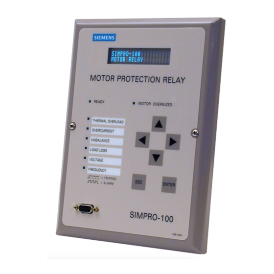
5 Front-Panel Operation Front-Panel Layout The SIMPRO-100 Relay front-panel interface consists of LEDs, a vacuum fluorescent display, a six-button keypad, and an EIA-232 serial port connector. The front-panel layout is shown in Figure 5.1. Figure 5.1 SIMPRO-100 Relay Front Panel PRIM-2400C... -
Page 78: Normal Front-Panel Display
Front-Panel Operation SIMPRO-100 Normal Front-Panel Control the contents of these custom messages using the Display Message settings, described in Display “Front-Panel Display Message Settings”, page 67. If you wish to change the conditions In normal operation, the Relay Enabled LED under which the relay displays a message, refer should be lit. -
Page 79: Front-Panel Menus & Operations
5.4.1 Introduction Move down within a menu or data list. The SIMPRO-100 Relay front panel gives you While editing a setting value, decreases the access to most of the information that the relay value of the underlined digit. -
Page 80: Figure 5.6 Password Entry Screen
Front-Panel Operation SIMPRO-100 5.4.2.3 To Enter the Password Before you can perform a front-panel menu activity that is marked with the padlock symbol, Note: Use these steps to enter the correct you must enter the correct Access Level 2 password to execute an Access level 2 password once or assert input IN4. -
Page 81: Front-Panel Main Menu
Front-Panel Operation SIMPRO-100 5.4.2.4 To Correct Entry Errors 4. With the correct Access Level 2 password spelled in the upper line of the display, press 1. If the cursor in the upper line of the display is the {ESC} pushbutton to move the cursor blinking, press the {ESC} pushbutton once. -
Page 82: Figure 5.9 Main Menu: Start Motor Function
Front-Panel Operation SIMPRO-100 Figure 5.13 Main Menu: Set Relay Function Figure 5.9 Main Menu: Start Motor Function Figure 5.10 Main Menu: Emergency Restart Function Figure 5.14 Set Relay\Relay Elements Function Note: Within the list of setting categories, press the {ENTER} pushbutton to view or change specific settings within the category. - Page 83 Front-Panel Operation SIMPRO-100 Figure 5.20 Set Relay\Password Function Note: Edit the Access Level 2 password using the steps described in Section 5.4.2.2, Figure 5.16 Set Relay\Front Serial Port Settings page 78 for password entry. Remember that the relay password is case sensitive.
- Page 84 Front-Panel Operation SIMPRO-100 Figure 5.22 Meter Values Display Functions Figure 5.26 History Data\Clear History Function Figure 5.23 Meter Values Reset Functions Figure 5.27 Main Menu: Motor Statistics Function Figure 5.24 Main Menu: History Data Function Figure 5.28 Motor Statistics\Motor Use Data Function Figure 5.25 History Data\Display History Function...
- Page 85 Front-Panel Operation SIMPRO-100 Figure 5.30 Motor Statistics\Trip and Alarm Data Function Figure 5.34 Main Menu: Pulse Out Contact Function Figure 5.31 Motor Statistics\Reset Statistics Function Figure 5.35 Pulse Output Contact Menu Function. Figure 5.32 Main Menu: Status of Relay Function Figure 5.36 Main Menu: Reset Thermal Model...
- Page 86 Front-Panel Operation SIMPRO-100 Figure 5.38 Reset Learned Param\Reset Cooling Figure 5.39 Reset Learned Param\Reset Start Therm Time Function Cap Function PRIM-2400C...
-
Page 87: Ascii Serial Port Operation
6 ASCII Serial Port Operation Introduction • Terminal emulation software to control the computer serial port You can interact with the SIMPRO-100 Relay • SIMPRO-100 Relay through the front-panel interface or the serial port interface. This section describes the connections On most newer computers, the connector for the and commands used with the serial port interface;... -
Page 88: Connect Your Pc To The Relay
ASCII Serial Port Operation SIMPRO-100 Connect Your PC to the Relay Connect your PC serial port to the SIMPRO-100 Relay serial port using a cable having the pinout shown in Figure 6.1 or a null-modem cable. Figure 6.2 DB-9 Connector Pinout for EIA-232... -
Page 89: Configure Your Terminal Emulation Software
Flow Control XON/XOFF (software flow control) Hold down the Control <CNTRL> Q key and press Q. Table 6.2 SIMPRO-100 Relay Serial Communication Default Settings Hold down the Control XOFF <CNTRL> S key and press S. To change the port settings, use the front-panel Hold down the Control <CNTRL>... -
Page 90: Serial Port Access Levels
ASCII Serial Port Operation SIMPRO-100 Serial Port Access Command Summary Levels Table 6.4 lists the serial port commands associated with particular activities. All Access The available serial port commands are listed in Level 1 commands are also available in Access Table 6.4. -
Page 91: Command Explanations
Start motor on passwords. The factory default password for Access Level 2 is 100. Table 6.4 SIMPRO-100 Serial Port Command Summary The relay closes the ALARM b-contact for one second after a successful Level 2 access. If you The serial port command explanations that follow... -
Page 92: Analog (Level 2)
Pulse Remote Bit n for 1/4 cycle Description PRB n Command (MOMENTARY position) Display the most recent event report Table 6.5 SIMPRO-100 Relay Control at 1/4-cycle resolution. Subcommands EVE 2 Display the second event report at 1/4-cycle resolution. The following example shows the steps... -
Page 93: History (Level 1 Or 2)
ASCII Serial Port Operation SIMPRO-100 6.8.7 HISTORY If the requested load profile records do not exist, (Level 1 or 2) the relay responds No Load Profile Data HISTORY n displays event summaries. If no parameters are specified with the HISTORY 6.8.10... -
Page 94: Energy Metering: Meter E
ASCII Serial Port Operation SIMPRO-100 6.8.15 Energy Metering: METER E 6.8.20 METER RM (Level 1 or 2) When the relay is equipped with optional voltage Reset the maximum/minimum meter values using inputs, the METER E command displays the the MET RM command. -
Page 95: Msr (Level 1 Or 2)
ASCII Serial Port Operation SIMPRO-100 6.8.24 The password may include up to six characters. (Level 1 or 2) Valid characters consist of: A – Z, a – z, 0 – 9, -, Use the MSR (Motor Start Report) command to and . -
Page 96: Rlp (Level 2)
ASCII Serial Port Operation SIMPRO-100 6.8.30 6.8.32 SER R (Level 2) (Level 2) Use the RLP (Reset Learned Parameters) SER R removes the SER data from nonvolatile command at Access Level 2 to reset the learned memory. motor parameters. You can reset the learned motor stopped cooling time and the learned 6.8.33... -
Page 97: Show (Level 1 Or 2)
ASCII Serial Port Operation SIMPRO-100 When all the settings are entered, the relay The SHOW commands display only the enabled displays the new settings and prompts you for settings. To display all settings, including approval to enable them. Answer Y <ENTER> to disabled/hidden settings, append an A to the enable the new settings. -
Page 98: Status R (Level 2)
ASCII Serial Port Operation SIMPRO-100 6.8.37 STATUS R start the motor. Refer to Section B.5, page 144 (Level 2) for information on changing the factory default To reset the self-test status and restart the relay, logic. use the STA R command from Access Level 2. -
Page 99: Target R (Level 1 Or 2)
ALARM * Bit not used; reserved for future expansion. a See Table 9.1 on page 117 for additional information on the meaning of each target LED condition. Table 6.19 SIMPRO-100 Relay Word and Corresponding TAR Command Serial Port Automatic 6.8.41... - Page 100 ASCII Serial Port Operation SIMPRO-100 PRIM-2400C...
-
Page 101: Commissioning
Commissioning Procedure This procedure is a guideline to help you enter 1. Ensure that control power and ac signals are settings into the SIMPRO-100 Relay and verify removed from the SIMPRO-100 Relay by that it is properly connected. Modify the... - Page 102 • If you use open-delta potentials, set the test source phase angles as shown in 8. If you are using a SIMPRO-100-RTD External Figure 7.2, page 101. RTD Module, connect the fiber-optic cable to the module fiber-optic output. At the relay-end •...
- Page 103 Commissioning SIMPRO-100 • Use the front-panel Meter Values\Instantaneous Meter function or serial port METER command to verify that the relay is measuring the magnitude and phase angle of both voltage and current correctly, taking into account the relay PTR and CTR settings and the fact that the quantities are displayed in primary units.
- Page 104 15. When it is safe to do so, start the motor. typically indicates a single-phase voltage connection problem. 16. Verify the following ac quantities using the front-panel Meter Values\Instantaneous Meter The SIMPRO-100 Relay is now ready for or serial port METER command: continuous service. • Phase current magnitudes should be nearly equal.
-
Page 105: Selected Functional Tests
Table 7.2 Test Source Connections for Different Relay Configurations Figure 7.3 Three Voltage Source and Three Current Source Test Connections Note: Relays equipped with ac voltage inputs (Models SIMPRO-100-R or N-V) must be properly grounded for accurate voltage measurement. PRIM-2400C... -
Page 106: Phase Current Measuring Accuracy
Figure 7.4 Two Voltage Source and Three Current Source Test Connections Note: Relays equipped with ac voltage inputs 4. Turn on the current sources and increase the (Models SIMPRO-100-R or N-V) must be current applied to the relay. Use the properly grounded for accurate voltage front-panel Meter Values\Instantaneous Meter measurement. -
Page 107: Neutral Current Measuring Accuracy
Commissioning SIMPRO-100 7.3.3 Neutral Current Measuring 3. Set the current source phase angles to apply balanced three-phase currents. Refer to Accuracy Figure 7.1, page 100 for the correct angles that depend on the PHROT setting. 1. Connect one current source to the IN current input (5 A or 1 A, as indicated by the INTAP 4. -
Page 108: Motor Thermal Element Accuracy
Commissioning SIMPRO-100 7.3.5 Motor Thermal Element 4 • 10 = 40 seconds when applied three-phase current equals three times the motor full load Accuracy current setting, FLA. Use the front-panel Meter Values\Thermal & RTD Data function to view the Note: This test outlines steps to verify estimated Time to Thermal Trip during each test. -
Page 109: Rtd Input Measuring Accuracy
Commissioning SIMPRO-100 Desired % ANALOG Actual Meter Expected Meter Reading Expected Meter Reading Expected Meter Reading Output Command Reading (0-1 mA Range) (0-20 mA Range) (4-20 mA Range) ANA 0 1 0.0mA 0.0mA 4.0mA ANA 25 1 0.25mA 5.0mA 8.0mA ANA 50 1 0.5mA... -
Page 110: Power & Power Factor Measuring Accuracy
Commissioning SIMPRO-100 Expected Expected RTD Temperatures Resistance Temperature Temperature Value (ohms) Reading (°C) Reading (°F) 71.81 100.00 131.45 167.20 207.45 252.88 294.28 Table 7.10 100-Ohm Nickel RTD Type (RTDs 1 – 12) Expected Expected RTD Temperatures Resistance Temperature Temperature Value (ohms) Reading (°C) - Page 111 Commissioning SIMPRO-100 Applied Currents Real Power Reactive Power Power Factor and Voltages (kW) (kVar) (pf) PHROT = ABC Expected: Expected: Expected: P = 0.4523 • CTR • PTR Q = 0.2211 • CTR • PTR pf = 0.90 lag Ia = 2.5 A ∠-26°...
- Page 112 Commissioning SIMPRO-100 Applied Currents Real Power Reactive Power Power Factor and Voltages (kW) (kVar) (pf) PHROT = ABC Expected: Expected: Expected: P = 0.4677 • CTR • PTR Q = 0.2286 • CTR • PTR pf = 0.90 lag Ia = 2.5 A ∠-26°...
-
Page 113: Metering & Monitoring
Metering & Monitoring SIMPRO-100 8 Metering & Monitoring Introduction 8.1.1 Metering SIMPRO-100 Relay meter data fall into several The SIMPRO-100 Relay features metering categories: functions to display the present values of current and (if included) voltage and RTD • Instantaneous metering measurements. -
Page 114: Demand Metering
With RTD Monitoring or when All RTD Temperatures The demand metering function also records the the SIMPRO-100-RTD External RTD % Thermal Capacity peak values of each demand quantity. Module is connected Table 8.4 Thermal Meter Values 8.1.4... -
Page 115: Energy Metering
When voltage inputs are selected and connected, the relay records the real, reactive, and apparent energy consumed by the motor. Figure 8.1 Power Measurement Conventions In the SIMPRO-100 Relay, reported positive real power and energy are always into the motor. PRIM-2400C... -
Page 116: Load Profiling
Metering & Monitoring SIMPRO-100 Load Profiling Motor Operating Statistics The SIMPRO-100 Relay includes a built-in load profiling function that does not require any The SIMPRO-100 Relay retains useful configuration. The relay automatically records information regarding the protected motor. The selected quantities into nonvolatile memory every serial port MOTOR command and front-panel 15 minutes, synchronized to the quarter-hour. -
Page 117: Learned Parameters
Underfrequency • Overfrequency 8.4.3 Learned Parameters • The SIMPRO-100 Relay can learn two protection • Total parameters of the protected motor. When you connect the relay to monitor at least one motor Motor Start Report winding RTD and the ambient temperature, the relay can learn the cooling time of the protected motor when it is stopped. -
Page 118: Start Data
Metering & Monitoring SIMPRO-100 Motor Start Trending 8.5.2 Start Data The motor start data is taken every 5 cycles for Each time the relay stores a motor start report, it 3600 cycles, starting 5 cycles after the phase adds the motor start summary data (described in current magnitude exceeds 2.5 times Full Load... -
Page 119: Event Analysis
Frequency This LED remains on steadily after a trip that occurs while an over- or underfrequency element is picked up. Table 9.1 SIMPRO-100 Relay Front-Panel Target LED Definitions 9.2.1 Resetting Front-Panel Targets To reset the front-panel tripping targets, select the (described in Section 9.3, page 118) is... -
Page 120: Motor Energized Led
Starting If the motor was stopped and now positive-sequence current is greater than 2.5 Each time the SIMPRO-100 Relay trips, and in times the Full Load Amps’ setting, the relay response to other selected conditions, the relay declares the motor starting. The Motor captures motor current, voltage (if included), RTD Energized LED flashes. -
Page 121: Event Reports
Event Reports • Any of the programmable event triggering conditions occur (see below) The SIMPRO-100 Relay captures and stores The factory default logic settings include detailed information concerning the relay settings that cause the relay to trigger an measurements, protection element status, and event report when any of the following contact input/output status. -
Page 122: Retrieving Event Reports
VA or VAB Voltage measured by channel VA or VAB Table 9.3 EVE Command Options (primary V) The SIMPRO-100 Relay also provides a facility to VB or VBC Voltage measured by channel VB or VBC (primary V) allow you to download event report data using Modbus, protocol and the rear-panel serial port. - Page 123 Level 1 Residual Overcurrent Both IN5 and IN6 asserted. Element picked up and time delay expired. In 7 Contact input IN7 (from SIMPRO-100-RTD) asserted. Level 2 Residual Overcurrent Element picked up and time delay Table 9.5 Output, Input, and Element Event Report expired.
-
Page 124: Filtered & Unfiltered Event Reports
9.5.4 Filtered & Unfiltered Event Reports Recorder (SER) Report The SIMPRO-100 Relay samples the basic power system measurands (ac current and ac voltage) 16 times per power system cycle. The 9.6.1 SER Triggering relay filters the measurands to remove transient signals. -
Page 125: Retrieving Ser Reports
Event Analysis SIMPRO-100 9.6.3 Retrieving SER Reports Row 1 is the most recently triggered row and Row 512 is the oldest. Use the serial port SER The relay saves the latest 512 rows of the SER command to view the SER report by date or SER report in nonvolatile memory. -
Page 126: Example Event Report
Event Analysis SIMPRO-100 Example Event In Figure 9.1, the arrow (>) in the column following the IN or Vc column identifies the Report “trigger” row, the row that corresponds to the Date and Time values at the top of the event The example Event Report in Figure 9.1... - Page 127 Event Analysis SIMPRO-100 Figure 9.2 Example SER Report PRIM-2400C...
-
Page 128: Example Ser Report
Event Analysis SIMPRO-100 Example SER Report This example SER report (Figure 9.3) corresponds to the event report in Figure 9.1, page 124. Figure 9.3 Example SER Report The SER event report rows in Figure 9.3 are Figure 9.3. The SER event report in Figure 9.3 explained in the Table 9.7, numbered in... -
Page 129: 10 Maintenance & Troubleshooting
Repeat for the other output contacts. Make sure that each contact operates properly in its The SIMPRO-100 Relay does not require specific designated annunciation, control, or tripping routine tests, but your operational standards may circuit. -
Page 130: Alarm Output
Maintenance & Troubleshooting SIMPRO-100 10.2.2 ALARM Output • The relay generates a STATUS report at the serial port for failures. The ALARM output contact signals an alarm condition by going to its deenergized state. • The relay displays failure messages on the relay VFD display. -
Page 131: Troubleshooting Procedure
Maintenance & Troubleshooting SIMPRO-100 10.3 Troubleshooting 10.3.4 Relay Does Not Respond to Commands From Device Procedure Connected to Serial Port 10.3.1 Relay Enabled Front-Panel Possible Cause Solution LED Dark Communications device Verify cable connections. not connected to relay. Possible Cause... -
Page 132: Power Supply Fuse Replacement
Maintenance & Troubleshooting SIMPRO-100 10.4 Power Supply Fuse the nominal 10 years because the battery rarely has to discharge after the relay is installed. The Replacement battery cannot be recharged. If the relay does not maintain the date and time... -
Page 133: Firmware Upgrade Installation
However, if the upgrades to improve the performance of your new firmware version includes more settings relay. Since the SIMPRO-100 Relay stores than the old version, you will have to reenter firmware in flash memory, changing physical your old settings. - Page 134 Maintenance & Troubleshooting SIMPRO-100 7. Make a copy of the firmware currently in the 11. Start the file transfer by selecting the send file relay. This is recommended in case the new option in your communication software. Use firmware download is unsuccessful. To make...
-
Page 135: Factory Assistance
10.7 Factory Assistance Set the relay passwords via the PAS command. Siemens 13. Execute the STATUS command to verify all Power Transmission & Distribution relay self-test results are okay. 7000 Siemens Road Wendell, NC 27591 Voice: 877.217.4943 Fax: 919.965.2552 PRIM-2400C... - Page 136 Maintenance & Troubleshooting SIMPRO-100 PRIM-2400C...
-
Page 137: A Firmware Versions
Firmware Versions SIMPRO-100 A Firmware Versions To find the firmware revision number in your relay, view the status report using the serial port STATUS command or the front-panel Status of Relay function. The status report displays the FID label with the Part/Revision number in bold, for... - Page 138 Firmware Versions SIMPRO-100 PRIM-2400C...
-
Page 139: B Control Equations & Relay Logic
B.2.1 Data Acquisition & Filtering applications within the SIMPRO-100 Relay. Specific topics include: The SIMPRO-100 Relay passes ac current and (if • General Operation of the Relay included) voltage signals through low-pass filters to remove signals above the eighth harmonic. -
Page 140: Control Equations
Control Equations & Relay Logic SIMPRO-100 B.2.4 Control Equations again. During this free time, the relay performs background tasks such as: After evaluating the fixed logic, the relay • Self-testing evaluates the control equations, then controls the relay output contacts. See Section B.4, page 141 •... - Page 141 SV4T TRIP OUT1 OUT2 OUT3 ALARM Table B.1 SIMPRO-100 Relay Word Bits Definition STARTING Asserts when protected motor is starting (current is greater than 2.5 times motor rated full load current). RUNNING Asserts when motor is running. STOPPED Asserts when motor is stopped (current is less than 3% of motor rated full load current).
- Page 142 Control Equations & Relay Logic SIMPRO-100 Definition Phase Reversal Trip. Asserts when the relay detects a phase reversal condition, if phase reversal tripping is enabled by the relay settings. TRGTR Target Reset. Asserts for one quarter-cycle when you execute a front-panel or serial port target reset command.
-
Page 143: Control Equations
Control equation variable 1 – 4 with settable pickup and dropout time delay. SV2T SV3T SV4T Contact inputs IN1 – IN6. Contact input IN7. Available only when using SIMPRO-100-RTD External RTD module. Reserved for future use. TRIP Contact outputs TRIP, OUT1, OUT2, OUT3, and ALARM. OUT1... -
Page 144: Control Equation Operators
Control Equations & Relay Logic SIMPRO-100 B.4.1 Control Equation B.4.1.2 Control Equation OR Operator [+] Operators Use the plus [+] symbol to denote logical OR Build control equation settings using logic similar operations. When you use the [+] between two... -
Page 145: All Control Equations Must Be Set
Control Equations & Relay Logic SIMPRO-100 When frequency goes above the corresponding B.4.1.6 Control Equation NOT pickup level 81D1P, Relay Word bit 81D1T Operator [!] deasserts and an event report is generated (if the Use the NOT operator [!] to invert a single Relay... -
Page 146: Control Equation Limitations
Control Equations & Relay Logic SIMPRO-100 Factory Default B.4.3 Control Equation Limitations Logic Settings Each single control equation setting is limited to When you use the factory default logic by setting 17 Relay Word bits that you can combine FACTLOG equal to Y, the relay hides the logic together with the control equation operators listed settings and default settings shown in Figure B.3,... - Page 147 Control Equations & Relay Logic SIMPRO-100 Figure B.3 Display Message Variables PRIM-2400C...
-
Page 148: Front-Panel Display Message Configuration
Once SV1T is asserted, it remains asserted for There are four text display messages available in SV1DO seconds after the SV1 control equation the SIMPRO-100 Relay. Each text display has result becomes a logical 0. Figure B.4 illustrates two complementary screens. -
Page 149: Latch Control Switch States Are Retained During Power Loss
Control Equations & Relay Logic SIMPRO-100 B.8.2 Make Latch Control Switch Four latch control switches in the SIMPRO-100 Relay provide latching relay type functions. Settings With Care The latch bit states are stored in nonvolatile memory so they can be retained during power loss. -
Page 150: Unlatch Trip
Control Equations & Relay Logic SIMPRO-100 B.9.2 Unlatch Trip • One of the following occurs: Following a fault, the trip signal is maintained until – Unlatch Trip control equation setting all of the following conditions are true: ULTRIP asserts to logical 1 •... -
Page 151: Breaker Auxiliary Contact Control Equation Setting
Control Equations & Relay Logic SIMPRO-100 B.10 Breaker Auxiliary The relay automatically locks out the motor by asserting the trip signal under any of the following Contact Control conditions: Equation Setting • Antibackspin Lockout The breaker auxiliary contact control equation... -
Page 152: Program An Output Contact For Motor Starting
Control Equations & Relay Logic SIMPRO-100 The START Relay Word bit remains asserted for When the Emergency Restart Relay Word bit 0.5 seconds, unless the relay trips. If the relay asserts, the relay: trips before the 0.5 second timer expires, the •... -
Page 153: Speed Switch Control Equation Setting
Control Equations & Relay Logic SIMPRO-100 B.13 Speed Switch B.16 Remote Control Control Equation Switches Setting Remote control switches do not have settings; they are operated via the serial communications The speed switch control equation, SPEEDSW, port only (see Section 6.8.4, page 90). -
Page 154: Remote Bit Application Ideas
Control Equations & Relay Logic SIMPRO-100 B.17 Selected Relay B.16.1 Remote Bit Application Ideas Logic Diagrams With control equations, you can use the remote bits to trip or start the motor or to open, close, or pulse relay output contacts for other purposes. - Page 155 Control Equations & Relay Logic SIMPRO-100 Figure B.12 Current Unbalance Element Logic Figure B.13 Phase Reversal Element Logic PRIM-2400C...
- Page 156 Control Equations & Relay Logic SIMPRO-100 Figure B.14 Overcurrent Element Logic Figure B.15 Power Factor Elements Logic PRIM-2400C...
- Page 157 Control Equations & Relay Logic SIMPRO-100 Figure B.16 Overvoltage Element Logic PRIM-2400C...
- Page 158 Control Equations & Relay Logic SIMPRO-100 Figure B.17 Over/Underfrequency Element Logic Figure B.18 Load-Jam Elements Logic PRIM-2400C...
- Page 159 Control Equations & Relay Logic SIMPRO-100 Figure B.19 Load-Loss Logic; No Voltage Option Figure B.20 Load-Loss Logic; Voltage Option Included PRIM-2400C...
- Page 160 Control Equations & Relay Logic SIMPRO-100 Figure B.21 Reactive Power Elements Logic Figure B.22 Speed Switch Tripping Logic PRIM-2400C...
-
Page 161: Modbus Rtu Communications Protocol
Introduction Modbus RTU Communications This appendix describes Modbus RTU Protocol communications features supported by the SIMPRO-100 Relay at the rear-panel EIA-485 port. Complete specifications for the Modbus C.2.1 Modbus Queries protocol are available from Modicon on their web site: www.modicon.com. -
Page 162: Supported Modbus Function Codes
Read Input Status Check Read Holding Registers Read Input Registers The SIMPRO-100 Relay calculates a 2-byte CRC Force Single Coil value using the device address, function code, Preset Single Register and data fields. It appends this value to the end of every Modbus response sent. -
Page 163: Read Coil Status Command
2 bytes Number bits to read 2 bytes CRC-16 for message 2 bytes CRC-16 for message A Successful SIMPRO-100 Relay Response will have A Successful SIMPRO-100 Relay Response will have the Following Format the Following Format 1 byte Slave address... -
Page 164: Read Holding Registers Command
2 bytes Number of registers to read 1 byte Slave address 2 bytes CRC-16 for message 1 byte Function code (03h) A Successful SIMPRO-100 Relay Response will 2 bytes Starting register address have the Following Format 2 bytes Number of registers to read... -
Page 165: Force Single Coil Command
05h Force Single 06h Preset Single Coil Command Register Command The SIMPRO-100 Relay uses this function code The SIMPRO-100 Relay uses this function to for a variety of data control purposes. Specifically, allow a Modbus master to write directly to a you can use it to clear archive records, operate database register. -
Page 166: Read Exception Status Command
08h Loopback Status Command Diagnostic Command The SIMPRO-100 Relay uses this function to allow a Modbus master to read the present status The SIMPRO-100 Relay uses this function to of the relay and protected motor. allow a Modbus master to perform a diagnostic test on the Modbus communications channel and relay. -
Page 167: Preset Multiple Registers Command
Byte count bytes of data function and associated parameters, and the 2 bytes CRC-16 for message function code used to initiate the code. A successful SIMPRO-100 relay response will have the following format: Parameter 2 of Command Code 6 and 1 byte... - Page 168 ™ Modbus RTU Communications Protocol SIMPRO-100 Command Modbus Function Function Parameter Definition Code Code Start No Parameters 06h, 10h Stop No Parameters 06h, 10h Emergency Restart No Parameters 06h, 10h Reset Trip, Targets No Parameters 06h, 10h Pulse Output Contacts...
-
Page 169: Setting The Relay Time/Date Using Modbus
Time/Date Using Status Using Modbus Modbus The SIMPRO-100 Relay Modbus Register Map The SIMPRO-100 Relay Modbus Register Map provides fields that allow you to set the relay provides fields that allow you to read the present clock and calendar using Modbus Function Code relay self-test results. -
Page 170: User-Defined Modbus Data Region
2. Refer to Table C.19 on page 187, and list the Equal To From Channel address of each quantity. 3. Set the SIMPRO-100 Relay User Map Addresses (00D0h – 014Ch) equal to the addresses of the desired quantities using the SIMPRO-PC software and a PC connected to the front-panel serial port. -
Page 171: Modbus Register Map
™ Modbus RTU Communications Protocol SIMPRO-100 C.17 Modbus Register Map Address Field Sample High Step Type (hex) PRODUCT ID 0000 FID string 0001 0002 0003 0004 0005 0006 0007 0008 0009 000A 000B 000C 000D 000E 000F 0010 0011 0012... - Page 172 ™ Modbus RTU Communications Protocol SIMPRO-100 Address Field Sample High Step Type (hex) 0025 Terminal ID MOTOR RELAY 0026 0027 0028 0029 002A 002B 002C 002D 002E 002F Reserved COMMANDS 0030 Command Function Code 0031 Parameter 1 0032 Parameter 2 0033 –...
- Page 173 ™ Modbus RTU Communications Protocol SIMPRO-100 Address Field Sample High Step Type (hex) USER MAP ADDRESSES 00D0 User Map Address # 1 00D1 User Map Address # 2 00D2 User Map Address # 3 014A User Map Address # 123...
- Page 174 ™ Modbus RTU Communications Protocol SIMPRO-100 Address Field Sample High Step Type (hex) 0180 Vca Rms Voltage 0 if no voltage option 65535 0181 Average Rms Voltage 0 if no voltage option 65535 0182 kW3P Power 0 if no voltage option...
- Page 175 ™ Modbus RTU Communications Protocol SIMPRO-100 Address Field Sample High Step Type (hex) 01A6 Starts This Hour 01A7 Reserved 01A8 Reserved 01A9 Reserved 01AA Reserved 01AB Reserved 01AC Reserved 01AD Reserved 01AE Reserved 01AF Reserved ENERGY METERING 01B0 MWhr 0 if no voltage option...
- Page 176 ™ Modbus RTU Communications Protocol SIMPRO-100 Address Field Sample High Step Type (hex) 01CB yyyy 65535 01CC Last Reset Time hh, mm 0, 0 23, 59 1, 1 01CD ssss 5999 • 0.01 01CE Reserved 01CF Reserved PEAK DEMAND METERING...
- Page 177 ™ Modbus RTU Communications Protocol SIMPRO-100 Address Field Sample High Step Type (hex) 01F0 Ib Min Current Date mm, dd (FFFFh if reset) 1, 1 12, 31 1, 1 01F1 yyyy (FFFFh if reset) 65535 01F2 Ib Min Current Time...
- Page 178 ™ Modbus RTU Communications Protocol SIMPRO-100 Address Field Sample High Step Type (hex) RTD MAX/MIN METERING 0220 RTD # 1 Max Temperature FFFFh if reset or no RTD See Note 3 See Note 3 0221 RTD # 1 Max Temperature Date...
- Page 179 ™ Modbus RTU Communications Protocol SIMPRO-100 Address Field Sample High Step Type (hex) 0246 RTD # 4 Min Temperature Time hh, mm (FFFFh if reset) 0, 0 23, 59 1, 1 0247 ssss (FFFFh if reset) 5999 • 0.01 0248...
- Page 180 ™ Modbus RTU Communications Protocol SIMPRO-100 Address Field Sample High Step Type (hex) 026D yyyy (FFFFh if reset) 65535 026E RTD # 8 Min Temperature Time hh, mm (FFFFh if reset) 0, 0 23, 59 1, 1 026F ssss (FFFFh if reset) 5999 •...
- Page 181 ™ Modbus RTU Communications Protocol SIMPRO-100 Address Field Sample High Step Type (hex) 0294 RTD # 12 Min Temperature Date mm, dd (FFFFh if reset) 1, 1 12, 31 1, 1 0295 yyyy (FFFFh if reset) 65535 0296 RTD # 12 Min Temperature Time hh, mm (FFFFh if reset)
- Page 182 ™ Modbus RTU Communications Protocol SIMPRO-100 Address Field Sample High Step Type (hex) 02B7 Vca Max Voltage Time hh, mm (FFFFh if reset) 0, 0 23, 59 1, 1 02B8 ssss (FFFFh if reset) 5999 • 0.01 Vca Min Voltage...
- Page 183 ™ Modbus RTU Communications Protocol SIMPRO-100 Address Field Sample High Step Type (hex) 02DA Min kVAR3P Power Time hh, mm (FFFFh if reset) 0, 0 23, 59 1, 1 02DB ssss (FFFFh if reset) 5999 • 0.01 Max kVA3P Power...
- Page 184 ™ Modbus RTU Communications Protocol SIMPRO-100 Address Field Sample High Step Type (hex) 02FF Avg Running Current 65535 0300 Avg Running kW 0 if no voltage option 65535 0301 Avg Running kVAR In 0 if no voltage option 65535 0302...
- Page 185 ™ Modbus RTU Communications Protocol SIMPRO-100 Address Field Sample High Step Type (hex) 0326 Unbalance Current Trip Count 65535 0327 Phase Fault Trip Count 65535 0328 Ground Fault Trip Count 65535 0329 Speed Switch Trip Count 65535 032A Undervoltage Trip Count...
- Page 186 ™ Modbus RTU Communications Protocol SIMPRO-100 Address Field Sample High Step Type (hex) 034D yyyy 65535 034E 2nd Latest Start Time hh, mm 0, 0 23, 59 1, 1 034F ssss 5999 • 0.01 0350 3rd Latest Accel Time seconds 65535 •...
- Page 187 ™ Modbus RTU Communications Protocol SIMPRO-100 Address Field Sample High Step Type (hex) 037A 037B 037C 037D 037E 037F 0380 0381 0382 65535 0383 65535 0384 65535 0385 65535 0386 65535 0387 65535 0388 Hottest Winding RTD See Note 1...
- Page 188 ™ Modbus RTU Communications Protocol SIMPRO-100 Address Field Sample High Step Type (hex) 03A9 1 3/4 Cycle -32768 32767 03AA 2 Cycle -32768 32767 03AB 2 1/4 Cycle -32768 32767 03AC 2 2/4 Cycle -32768 32767 03AD 2 3/4 Cycle...
- Page 189 8000h = RTD shorted Event Type Strings 7fffh = RTD open Thermal Trip 7ffch = SIMPRO-100-RTD Locked Rotor Trip Communication Failure Load Loss Trip 7ff8h = SIMPRO-100-RTD Load Jam Trip Self-Test Status Failure...
- Page 190 ™ Modbus RTU Communications Protocol SIMPRO-100 Event Type Strings Undervoltage Trip Overvoltage Trip Underpower Trip Power Factor Trip Reactive Power Trip Phase Reversal Trip Underfrequency Trip Overfrequency Trip RTD Trip TRIGGER Table C.20 Event Type Strings PRIM-2400C...
-
Page 191: Dsimpro-Pc Compatibility Features
SIMPRO-100 D SIMPRO-PC Compatibility Features Introduction Fast Binary Message Lists This appendix describes communication features that the SIMPRO-100 Relay serial ports support when they are configured for ASCII Request communications. These functions are not Response From Relay to Relay provided on the relay EIA-485 port when it is ™... -
Page 192: Fast Binary Message Definitions
SIMPRO-PC Compatibility Features SIMPRO-100 Fast Binary Message In response to the A5C1 request, the SIMPRO-100 Relay sends the block shown in Definitions Table D.4. In response to the A5C0 request, the relay sends Data Description the block shown in Table D.3. - Page 193 SIMPRO-PC Compatibility Features SIMPRO-100 Data Description Data Description Scale factor type Analog channel type 0000 Scale factor offset in Fast Meter message Scale factor type 494300000000 Analog channel name (IC) 0000 Scale factor offset in Fast Meter message Analog channel type...
- Page 194 SIMPRO-PC Compatibility Features SIMPRO-100 In response to the A5C2 or A5C3 request, the Data Description SIMPRO-100 Relay sends the block shown in Analog channel type Table D.6. Scale factor type 0000 Scale factor offset in Fast Meter message Data Description 4F5448000000 Analog channel name (OTH) [Hottest Other RTD Temp.]...
- Page 195 SIMPRO-PC Compatibility Features SIMPRO-100 In response to the A5D2 or A5D3 request, the Data Description SIMPRO-100 Relay sends the block shown in 494700000000 Analog channel name (IG) Table D.7. Analog channel type Scale factor type Data Description 0000 Scale factor offset in Fast Meter message...
-
Page 196: A5B9 Fast Meter Status Acknowledge Message
SIMPRO-PC Compatibility Features SIMPRO-100 D.3.1 A5B9 Fast Meter Status The SIMPRO-100 Relay performs the specified remote bit operation if the following conditions are Acknowledge Message true: In response to the A5B9 request, the • The Operate code is valid. SIMPRO-100 Relay clears the Fast Meter (message A5D1) Status Byte. -
Page 197: A5E0 Fast Operate Remote Bit Control
D.3.4 ID Message Clear RB2 In response to the ID command, the Clear RB3 SIMPRO-100 Relay sends the firmware ID, boot Clear RB4 code ID, relay RID setting, the Modbus device Set RB1 code, part number, and configuration as Set RB2 described below. -
Page 198: Dna Message
Byte in the A5D1 message. The first name is the first name is associated with the MSB and the last MSB and the last name is the LSB. The BNA name with the LSB. The SIMPRO-100 Relay message is: DNA message is: where: •... -
Page 199: Cascii Command
–"I" Integer data To obtain the configuration message for the compressed ASCII commands available in a –"F" Floating point data Siemens relay, type CAS <CR>. –"mS" String of maximum m characters The SIMPRO-100 Relay sends: (e.g., 10S for a 10 character string) –"yyyy"... -
Page 200: Simpro-100 Relay Command Response Contents
SIMPRO-100 D.5.2 SIMPRO-100 Relay Command Response Contents Display the SIMPRO-100 Relay compressed ASCII configuration message by typing CAS <CR>. The relay replaces the items in italics with the actual relay data. The SIMPRO-100 Relay sends: See Section D.3.5, page 196 for definition of the "Names of elements in the Relay Word separated... -
Page 201: Cstatus Command
The relay replaces the items in italics with the actual relay data. CSTATUS Command The SIMPRO-100 Relay sends: Display status data in compressed ASCII format by typing CST <CR>. The relay replaces the items in italics with the actual relay data. - Page 202 • "VAB", "VBC", and "VCA" are replaced by “VA”, “VB”, and “VC” in the event body The SIMPRO-100 Relay sends: when phase-neutral potentials are applied. They are replaced by “*” when voltages are not included. •...
- Page 203 A typical HEX-ASCII Relay Word is shown below: The SIMPRO-100 Relay sends: Each byte in the HEX-ASCII Relay Word reflects the status of 8 Relay Word bits. The order of the labels in the “Names of elements in the relay word separated by spaces”...
- Page 204 ASCII format by typing CME M <CR>. The relay replaces the items in italics with the actual relay data. The SIMPRO-100 Relay sends: Voltage and power labels are replaced with “*” if the optional voltage inputs are not included. RTD labels are replaced with “*”...
- Page 205 • "CALC TIME" is the calculated time to The SIMPRO-100 Relay sends: thermal trip in seconds. • "MINUTES" is the number of minutes since the last motor start.
- Page 206 SIMPRO-PC Compatibility Features SIMPRO-100 PRIM-2400C...
- Page 207 • Weights the heating effects of positive- and negative-sequence current equally when the motor is starting The SIMPRO-100 Relay provides effective motor thermal protection using a patented protection • Models the heat lost to the surroundings algorithm. The relay offers three convenient when the motor is running methods to set the thermal element.
- Page 208 Motor Thermal Element SIMPRO-100 The purpose of motor thermal protection is to The SIMPRO-100 Relay thermal element always allow the motor to start and run within the operates in one of two modes: starting or running. manufacturer’s published guidelines, but trip if...
- Page 209 Motor Thermal Element SIMPRO-100 Where: Heat Source = I • K • K R1 = Positive-sequence rotor Equation E.1 resistance at slip S = 1 Heating factors K and K are defined by the positive-sequence rotor resistance and R0 = Positive-sequence rotor negative-sequence rotor resistance, respectively.
- Page 210 To. two states representing the starting and running When a successful motor start occurs and states of the motor. The SIMPRO-100 Relay positive-sequence current drops below 2.5 times thermal element automatically selects which state full load current, the relay switches from the...
- Page 211 Motor Thermal Element SIMPRO-100 Motor Running Protection Figure E.6 Calculating the Normal Operating Energy Using Locked Rotor Trip Times Figure E.6 shows a graphical representation of Figure E.5 Motor Running Thermal Element With the problem and its solution. The motor normal...
- Page 212 Given a motor with the following Capacity Values characteristics, calculate the starting and running thermal model trip thresholds. Several of the SIMPRO-100 Relay reporting Service Factor, functions include a % Thermal Capacity value. At SF = 1.15 all times, the relay calculates the percent thermal capacity using Equation E.9.
- Page 213 Note: Since the Thermal Capacity Used to Start The SIMPRO-100 Relay provides two facilities to percentage is based on the starting help ensure that a motor start is not attempted thermal element trip threshold, the relay while the motor is still too hot to be started safely.
- Page 214 Motor Thermal Element SIMPRO-100 PRIM-2400C...
- Page 215 SIMPRO-100 Relay Settings Sheets SIMPRO-100 F SIMPRO-100 Relay Settings Sheets Relay Settings Phase Rotation Range: ABC, ACB (Factory Defaults, Model 100101X) PHROT = [ABC] F.1.1 General Data Nominal Frequency Relay Identifier Range: 50, 60 Hz Range: 20 Characters FNOM =...
- Page 216 SIMPRO-100 Relay Settings Sheets SIMPRO-100 F.1.2 Thermal Model Elements F.1.2.2 Thermal Element Settings when Setting Method = GENERIC (Hidden when SETMETH = GENERIC (Hidden when SETMETH = RATING or or USER GENERIC) Setting Method Full Load Amps Range: Rating, Generic, User Range: 2.50 –...
- Page 217 SIMPRO-100 Relay Settings Sheets SIMPRO-100 Time to Trip at 1.30 x FLA Time to Trip at 4.50 x FLA Range: 1.0 – 6000.0 s, NP Range: 1.0 – 6000.0 s, NP TTT130 = TTT450 = [Hidden] [Hidden] Time to Trip at 1.40 x FLA Time to Trip at 5.00 x FLA...
- Page 218 SIMPRO-100 Relay Settings Sheets SIMPRO-100 The balance of Thermal Element Settings are used Level 2 Phase O/C Time Delay regardless of setting method. Range: 0.00 – 400.00 s Thermal Capacity Alarm Pickup 50P2D = [Hidden] Range: 50% – 100% TCAPU =...
- Page 219 SIMPRO-100 Relay Settings Sheets SIMPRO-100 F.1.6 Load-Loss Element Negative-Sequence O/C Pickup Range: OFF, 0.25 – 100.00 A; ITAP = 5 A Settings Range: OFF, 0.05 – 20.00 A; ITAP = 1 A (Hidden when voltage option available.) 50QP = [OFF] Load-Loss Alarm Threshold Range: OFF, 30 –...
- Page 220 SIMPRO-100 Relay Settings Sheets SIMPRO-100 F.1.9 Speed Switch Tripping Load-Loss Alarm Time Delay Range: 0.00 – 400.00 s Time Delay Setting LLADLY = [5.00] Speed Switch Trip Time Delay Range: OFF, 0.50 – 400.00 s Load-Loss Trip Time Delay SPDSDLY = Range: 0.00 –...
- Page 221 SIMPRO-100 Relay Settings Sheets SIMPRO-100 RTD Location RTD Type Range: WDG, BRG, AMB, OTH, NONE Range: PT100, NI100, NI120, CU10 RTD6LOC = RTD3TY = [Hidden] [Hidden] RTD Location RTD Type Range: WDG, BRG, AMB, OTH, NONE Range: PT100, NI100, NI120, CU10...
- Page 222 SIMPRO-100 Relay Settings Sheets SIMPRO-100 F.1.13 RTD Temperature Settings RTD Trip Temperature Range: OFF, 0° – 250°C (Hidden when RTDOPT = NONE) OFF, 32° – 482°F RTD Trip Temperature TRTMP5 = [Hidden] Range: OFF, 0° – 250°C OFF, 32° – 482°F...
- Page 223 SIMPRO-100 Relay Settings Sheets SIMPRO-100 RTD Alarm Temperature Enable Bearing Trip Voting Range: OFF, 0° – 250°C Range: Y, N OFF, 32° – 482°F EBRNGV = [Hidden] ALTMP9 = [Hidden] Enable RTD Biasing (Hidden if not RTDnLOC = AMB, or if...
- Page 224 SIMPRO-100 Relay Settings Sheets SIMPRO-100 F.2.3 Undervoltage (U/V) VAR Alarm Time Delay (Hidden if NVARAP = OFF) Range: 0.00 – 400.00 s Elements (Hidden if no voltage option VARAD = [Hidden] or if DELTA_Y = D) Level 1 Phase U/V Pickup Negative VAR Trip Pickup Range: OFF, 1 –...
- Page 225 SIMPRO-100 Relay Settings Sheets SIMPRO-100 Phase Underpower Trip Time Delay Power Factor Trip Time Delay (Hidden if 55LDTP = OFF) (Hidden if 37PTP = OFF) Range: 0.00 – 400.00 s Range: 0.00 – 400.00 s 55TD = [Hidden] 37PTD =...
- Page 226 SIMPRO-100 Relay Settings Sheets SIMPRO-100 Output F.3.3 Front-Panel Display Message Settings Configuration Display Messages F.3.1 Analog Output Settings Range: 20 Characters; enter NA to null DM1_1 = [SIMPRO-100] Analog Output Signal Type Range: 0 – 1 mA, 0 – 20 mA, 4 – 20 mA...
- Page 227 SIMPRO-100 Relay Settings Sheets SIMPRO-100 F.3.5 Antibackspin Setting Stop Bits Range: 1, 2 Antibackspin Starting Delay STOP = Range: 0 – 60 min ABSDLY = Timeout Range: 0 – 30 min T_OUT = [15] F.3.6 Factory Logic Settings Send Auto Messages to Port...
- Page 228 SIMPRO-100 Relay Settings Sheets SIMPRO-100 SER Settings SER3 Range: 24 Relay Word bits, separated by commas. (SET R) Use NA to disable setting. SER3 = [RTDFLT, WDGALRM, WDGTRIP, BRGALRM, BRGTRIP, F.5.1 SER Trigger Settings AMBALRM, AMBTRIP, OTHALRM, OTHTRIP, 81D1T, 81D2T, 81D3T,...
- Page 229 SIMPRO-100 Relay Settings Sheets SIMPRO-100 F.5.3 Alias Settings ALIAS10 = [49T THERMAL_TRIP PICKUP DROPOUT] (Hidden when EALIAS = N, ALIAS# > EALIAS setting are hidden.) Note: Relay Word bit (space) Alias (space) ALIAS11 = Asserted text (space) Alias and text...
- Page 230 SIMPRO-100 Relay Settings Sheets SIMPRO-100 PRIM-2400C...
- Page 231 G Residual/Ground Element Alias N Neutral/Ground Element User assigned name of a Relay Word bit used in the SIMPRO-100 Relay Sequential Events Q Negative-Sequence (3I2) Element Recorder (SER) function. The assigned alias appears in the SER report in place of the...
- Page 232 Items in sequence; the second immediately remove a short-circuit or closed contact from following the first. a SIMPRO-100 Relay input. To clear a logic condition to its false state (logical 0). To open CR_RAM a normally-open output contact. To close a Abbreviation for Critical RAM.
- Page 233 Glossary SIMPRO-100 Delta As used in this instruction manual, a phase-to-phase connection of voltage transformers for electrical measuring Fail-Safe purposes. Typically, two voltage transformers Refers to an output contact that is energized are used with one primary lead of the first...
- Page 234 Measured A-, B-, and C-phase currents. Learned Motor Cooling Time Residual current, calculated from the sum of A motor parameter that the SIMPRO-100 the phase currents. In normal, balanced Relay can calculate using data collected over operation, this current is very small or zero.
- Page 235 Max/Min Meter deenergized. Type of meter data presented by the SIMPRO-100 Relay that includes a record of the maximum and minimum of each value, along with the date and time that each maximum and minimum occurred.
- Page 236 Glossary SIMPRO-100 Phase Rotation Reactive Power Element The sequence of voltage or current phasors A motor protection element that can trip the in a multi-phase electrical system. In an ABC protected motor if the measured reactive phase rotation system, the B-phase voltage power exceeds a user settable threshold.
- Page 237 Device. An RTD is made of a metal having a precisely known resistance and temperature Underfrequency Element coefficient of resistance. The SIMPRO-100 A protection element that causes the relay to Relay and SIMPRO-100-RTD External trip when the measured electrical system...
- Page 238 Glossary SIMPRO-100 As used in this instruction manual, a phase-to-neutral connection of voltage transformers for electrical measuring purposes. Three voltage transformers are used with one primary lead of the first transformer connected to A-Phase and the other lead connected to ground. The second...
- Page 240 Siemens Power Transmission & Distribution, Inc. Distribution Automation Division 7000 Siemens Road Wendell, NC 27591 Toll Free: 800.347.6659 www.siemenstd.com Fax: 919.365.2552 © Document No. PRIM-2400C 2000 Siemens Power Transmission & Distribution, Inc. Printed in USA 1100 SIEMENS is a registered trademark of Siemens AG.
Need help?
Do you have a question about the SIMPRO-100 and is the answer not in the manual?
Questions and answers