Sign In
Upload
Manuals
Brands
Siemens Manuals
Relays
SIMPRO-100
Siemens SIMPRO-100 Manuals
Manuals and User Guides for Siemens SIMPRO-100. We have
1
Siemens SIMPRO-100 manual available for free PDF download: Instruction Manual
Siemens SIMPRO-100 Instruction Manual (240 pages)
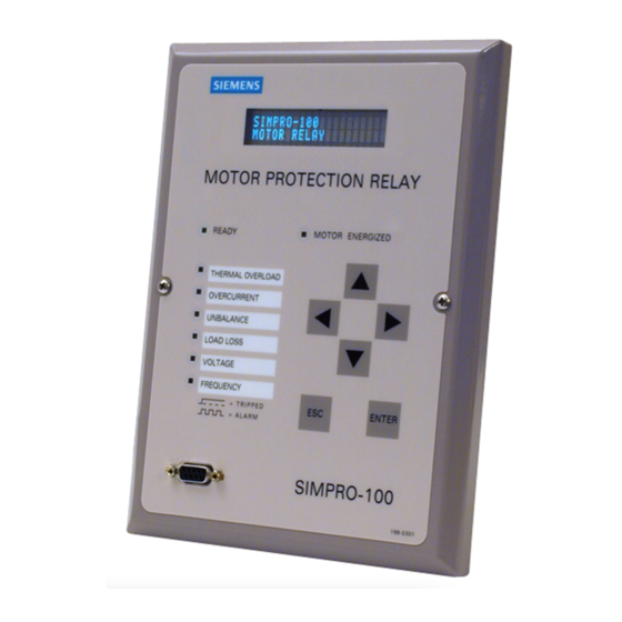
Motor Protection Relay
Brand:
Siemens
| Category:
Relays
| Size: 17.22 MB
Table of Contents
Table of Contents
3
List of Figures
13
List of Tables
17
1 Introduction & Specifications
21
Introduction
21
Typographic Conventions
22
SIMPRO-100 Relay Models
22
Table 1.1 SIMPRO-100 Relay Models
22
SIMPRO-100 Relay Applications
23
SIMPRO-100 Relay Protection Features
23
Figure 1.1 SIMPRO-100 Relay Applications
23
SIMPRO-100 Relay Monitoring & Reporting Features
24
Relay Order Number
24
Create a Relay Order Number
24
Table 1.2 SIMPRO-100 Relay Order Number Creation Table
24
Communication Cables
25
Place a Request for Quotation or Order
25
SIMPRO-100 Relay Serial Number Label
25
Detailed Specifications
25
Figure 1.2 SIMPRO-100 Relay Serial Number Label
25
Standard Relay Features & Functions
25
Optional Features & Functions
27
Ratings, Type Tests, & Certifications
28
Reporting Functions
28
2 Installation
29
Panel Cut & Drill Plans
29
Figure 2.1 SIMPRO-100 Relay Mechanical Dimensions (Front and Top Views)
29
Relay Mounting
30
Relay Rear-Panel Diagram
30
Figure 2.2 SIMPRO-100 Relay Cut and Drill Dimensions
30
Figure 2.3 SIMPRO-100 Relay Panel Mounting Detail
30
Figure 2.4 SIMPRO-100 Relay Rear Panel
31
Figure 2.5 SIMPRO-100 Relay Left- and Right-Side Panel Drawings
31
Figure 2.6 Example AC Wiring Diagram, Four-Wire Wye Voltages and Ground CT
32
Figure 2.7 Example AC Wiring Diagram, Open-Delta Voltages and Residual in Connection
32
Relay Connections
33
Figure 2.8 Example AC Voltage Wiring Diagram, Single Phase-To-Phase Voltage
33
Figure 2.9 Example AC Voltage Wiring Diagram, Single Phase-To-Neutral Voltage
33
Input Power Connections
33
Relay Chassis Ground Connection
33
Contact Outputs
34
Current Transformer Inputs
34
Figure 2.10 Ground CT Placement
34
Ground Current Transformer Input
34
Figure 2.11 Contact Output Factory Default Wiring Diagram
35
Figure 2.12 Trip Contact Fail-Safe, Nonfail-Safe Wiring Options
36
Figure 2.13 Optional Motor Start Wiring Using Factory Default Settings for Output Contact OUT3
36
Analog Output
37
Contact Inputs
37
Figure 2.14 Contact Input Factory Default Wiring Diagram
37
Figure 2.15 Analog Output Wiring
38
Figure 2.16 RTD Input Wiring
38
Internal RTD Connections (Relay Models SIMPRO-100-R-V or N)
38
Table 2.1 Typical Maximum RTD Lead Length
38
AC Voltage Connections (Relay Models SIMPRO-100-R or N-V)
39
Communication Cables
39
Figure 2.17 Rear-Panel EIA-485 Serial Port Connections
39
SIMPRO-100-RTD Module
40
Fiber-Optic Connection to SIMPRO-100-RTD Module
40
RTD Connections at the SIMPRO-100-RTD Module
40
3 SIMPRO-PC Software
41
Introduction
41
System Requirements
41
Installation
41
Table 3.1 SIMPRO-PC Software System Requirements
41
4 Settings Calculation
43
Introduction
43
Application Data
44
Table 4.1 Access Level 2 Commands
44
General Data
45
Current Transformer (CT) Configuration Settings
45
Identifier Settings
45
Phase Rotation, Nominal Frequency Settings
45
Table 4.2 Identifier Settings
45
Table 4.3 CT Configuration Settings
45
Table 4.4 Phase Rotation, Nominal Frequency Settings
45
Figure 4.1 Phase Rotation Settings
46
Table 4.5 VT Configuration Settings
46
Voltage Transformer (VT) Configuration Settings (Relay Models SIMPRO-100-R-V or N)
46
Basic Motor Protection
47
Table 4.6 Thermal Element Configuration Settings, Setting Method = RATING
47
Thermal Model Element
47
Table 4.7 Thermal Element Configuration Settings, Setting Method = GENERIC
48
Figure 4.2 Generic Thermal Limit Curves, Cold Motor
50
Table 4.8 Generic Thermal Limit Curve Tripping Times from Reset Versus Multiples of Full Load Amps, Curves 1 - 10 (Thermal Limit Times in Seconds)
51
Table 4.9 Generic Thermal Limit Curve Tripping Times from Reset Versus Multiples of Full Load Amps, Curves 15, 20, 25, 30, 35, 40, 45 (Thermal Limit Times in Seconds)
51
Table 4.10 Thermal Element Configuration Settings, Setting Method = USER
52
Figure 4.3 3000 HP Example Motor Cold Thermal Limit Curve
53
Table 4.11 3000 HP Motor Thermal Limit Times
54
Table 4.12 Thermal Capacity Alarm Setting
55
Table 4.13 Thermal Capacity to Start Settings
55
Table 4.14 Motor Cooling Time Settings
55
Overcurrent Elements
56
Table 4.15 Overcurrent Element Settings
56
Figure 4.4 Ground Fault Currents Using a Window CT
57
Jogging Block Elements
57
Table 4.16 Jogging Block Element Settings
57
Load-Jam Elements
58
Load-Loss Elements
58
Table 4.17 Load-Jam Function Settings
58
Table 4.18 Load-Loss Element Settings, no Voltage Option
58
Table 4.19 Load-Loss Element Settings, with Voltage Option
58
Current Unbalance Elements
59
Phase Reversal Tripping
59
Table 4.20 Current Unbalance Element Settings
59
Table 4.21 Phase Reversal Tripping Setting
59
Speed Switch Tripping
60
RTD-Based Protection
60
RTD Configuration Settings
60
Table 4.22 Speed Switch Tripping Time Delay Setting
60
Table 4.23 RTD Configuration Settings
60
RTD Location Settings
61
RTD Type Settings
61
Table 4.24 RTD Location Settings
61
Table 4.25 RTD Type Settings
61
RTD Alarm & Trip Temperatures
62
Table 4.26 RTD Alarm and Trip Temperature Settings
62
Table 4.27 RTD Resistance Versus Temperature
64
Voltage-Based Protection (Relay Models SIMPRO-100-R or N-V)
65
Table 4.28 Under- and Overvoltage Settings, Phase-To-Phase Potentials
65
Table 4.29 Under- and Overvoltage Settings, Phase-To-Neutral Potentials
65
Under- & Overvoltage Elements
65
Reactive Power (VAR) Elements
66
Table 4.30 Reactive Power Element Settings
66
Underpower Elements
66
Frequency Elements
67
Power Factor Elements
67
Output Configuration
68
Analog Output Settings
68
Front-Panel Configuration Settings
68
Front-Panel Display Message Settings
69
Front-Panel Display Settings
69
Output Contact Fail-Safe, Trip Duration, & Starting Lockout Settings
69
Antibackspin Setting
70
Factory Logic Settings
70
Figure 4.5 Factory Tripping Logic
71
Figure 4.6 Factory Contact Output Logic
71
Serial Port Settings
72
Figure 4.7 Factory Contact Input Logic
72
Figure 4.8 Factory Event Triggering Logic
72
Serial Port Settings (Serial Port Command SET P F or SET P R)
72
Sequential Events Recorder (SER) Settings
73
SER Trigger Settings
74
SER Alias Settings
75
5 Front-Panel Operation
77
Front-Panel Layout
77
Figure 5.1 SIMPRO-100 Relay Front Panel
77
Normal Front-Panel Display
78
Front-Panel Automatic Messages
78
Figure 5.2 Default Meter Display Screen
78
Figure 5.3 Default Display Message Screen
78
Front-Panel Menus & Operations
79
Figure 5.4 Front-Panel Pushbuttons
79
Figure 5.5Access Level Security Padlock Symbol
79
Front-Panel Security
79
Introduction
79
Figure 5.6 Password Entry Screen
80
Front-Panel Main Menu
81
Figure 5.7 Activate Front-Panel Display
81
Figure 5.8 Front-Panel Main Menu
81
Figure 5.9 Main Menu: Start Motor Function
82
Figure 5.10 Main Menu: Emergency Restart Function
82
Figure 5.11 Main Menu: Stop Motor Function
82
Figure 5.12 Main Menu: Reset Trip/Targets Function
82
6 ASCII Serial Port Operation
87
Introduction
87
You will Need
87
Connect Your PC to the Relay
88
Configure Your Terminal Emulation Software
89
Using Terminal Commands
89
Serial Port Access Levels
90
Access Level 1
90
Access Level 2
90
Command Summary
90
Command Explanations
91
ACC & 2AC (Go to Access Level 1 or 2)
91
HELP (Level 1 or 2)
91
ANALOG (Level 2)
92
CONTROL (Level 2)
92
DATE (Level 1 or 2)
92
EVENT (Level 1 or 2)
92
Demand Metering: METER D
93
HISTORY (Level 1 or 2)
93
HISTORY R (Level 2)
93
Instantaneous Metering: METER K
93
LDP (Level 1 or 2)
93
LDP D (Level 1 or 2)
93
LDP R (Level 2)
93
METER (Level 1 or 2)
93
Energy Metering: METER E
94
Maximum/Minimum Metering: METER M
94
METER RD (Level 1 or 2)
94
METER RE (Level 1 or 2)
94
METER RM (Level 1 or 2)
94
METER RP (Level 1 or 2)
94
MOTOR (Level 1 or 2)
94
MOTOR R (Level 2)
94
Thermal & RTD Metering: METER T
94
MSR (Level 1 or 2)
95
MST (Level 1 or 2)
95
MST R (Level 2)
95
PASSWORD (Level 2)
95
PULSE (Level 2)
95
QUIT (Level 2)
95
RLP (Level 2)
96
SER (Level 1 or 2)
96
SER R (Level 2)
96
SET (Level 2)
96
SHOW (Level 1 or 2)
97
STATUS (Level 1 or 2)
97
STATUS Command Row & Column Definitions
97
STATUS R (Level 2)
98
STOP (Level 2)
98
STR (Level 2)
98
TARGET (Level 1 or 2)
98
TARGET R (Level 1 or 2)
99
TIME (Level 1 or 2)
99
TRIGGER (Level 1 or 2)
99
Serial Port Automatic Messages
99
7 Commissioning
101
Introduction
101
Relay Commissioning Procedure
101
Commissioning Procedure
101
Required Equipment
101
Selected Functional Tests
105
Test Connections
105
Phase Current Measuring Accuracy
106
Current Unbalance Element Accuracy
107
Neutral Current Measuring Accuracy
107
Analog Output Accuracy
108
Motor Thermal Element Accuracy
108
RTD Input Measuring Accuracy
109
Power & Power Factor Measuring Accuracy
110
8 Metering & Monitoring
113
Introduction
113
Instantaneous Metering
113
Metering
113
Demand Metering
114
Max/Min Metering
114
Thermal Metering
114
Energy Metering
115
Power Measurement Conventions
115
Load Profiling
116
Motor Operating Statistics
116
Average & Peak Data
116
Times & Totals
116
Alarm and Trip Counters
117
Learned Parameters
117
Motor Start Report
117
Summary Data
117
Report Format
118
Start Data
118
Motor Start Trending
118
9 Event Analysis
119
Introduction
119
Front-Panel Target Leds
119
Resetting Front-Panel Targets
119
Motor Energized LED
120
Front-Panel Messages
120
History Data & Event Summaries
120
Event Reports
121
Event Report Triggering
121
Event Report Data Column Definitions
122
Retrieving Event Reports
122
Filtered & Unfiltered Event Reports
124
Resetting the Event Report Buffer
124
Sequential Events Recorder (SER) Report
124
SER Trigger Condition Aliases
124
SER Triggering
124
Resetting the SER Report Buffer
125
Retrieving SER Reports
125
Example Event Report
126
Example SER Report
128
10 Maintenance & Troubleshooting
129
Routine Maintenance Checks
129
Contact Input Verification
129
Contact Output Verification
129
Meter Verification
129
Relay Status Verification
129
Self-Testing
129
Protection Disabled
129
ALARM Output
130
Troubleshooting Procedure
131
Cannot See Characters on Relay Front-Panel Display Screen
131
Relay Does Not Accurately Measure Voltages or Currents
131
Relay Does Not Respond to Commands from Device Connected to Serial Port
131
Relay Does Not Respond to Faults
131
Relay Enabled Front-Panel LED Dark
131
Power Supply Fuse Replacement
132
Real-Time Clock Battery Replacement
132
Firmware Upgrade Installation
133
Required Equipment
133
Upgrade Instructions
133
Factory Assistance
135
A Firmware Versions
137
B Control Equations & Relay Logic
139
Introduction
139
Relay Functional Overview
139
Data Acquisition & Filtering
139
Element Processing
139
Relay Word
139
Background Tasks
140
Control Equations
140
Relay Word Bits
140
Control Equations
143
Control Equation Operators
144
All Control Equations Must be Set
145
Control Equation Limitations
146
Factory Default Logic Settings
146
Front-Panel Display Message Configuration
148
Nondedicated Control Equation Variable Settings
148
Latch Control Switch Settings
148
Latch Control Switch States Are Retained During Power Loss
149
Make Latch Control Switch Settings with Care
149
Stop/Trip Logic
149
Initiate Trip
149
Unlatch Trip
150
Breaker Auxiliary Contact Control Equation Setting
151
Start and Emergency Restart Logic
151
Program an Output Contact for Motor Starting
152
ACCESS2 Control Equation Setting
152
Speed Switch Control Equation Setting
153
Event Triggering Control Equation
153
Contact Output Control
153
Remote Control Switches
153
Remote Bit Application Ideas
154
Remote Bit States Are Not Retained When Power Is Lost
154
Selected Relay Logic Diagrams
154
Modbus RTU Communications Protocol
161
Introduction
161
Modbus Queries
161
Modbus Responses
161
Cyclical Redundancy Check
162
Modbus Exception Responses
162
Supported Modbus Function Codes
162
Read Coil Status Command
163
Read Input Status Command
163
Read Holding Registers Command
164
Read Input Registers Command
164
Force Single Coil Command
165
Preset Single Register Command
165
Read Exception Status Command
166
Loopback Diagnostic Command
166
Preset Multiple Registers Command
167
Controlling Output Contacts & Remote Bits Using Modbus
167
Setting the Relay Time/Date Using Modbus
169
Reading the Relay Status Using Modbus
169
User-Defined Modbus Data Region
170
Reading Event Data Using Modbus
170
Modbus Register Map
171
DSIMPRO-PC Compatibility Features
191
Introduction
191
Fast Binary Message Lists
191
Fast Binary Message Definitions
192
A5B9 Fast Meter Status Acknowledge Message
196
A5E0 Fast Operate Remote Bit Control
197
A5E3 Fast Operate Breaker/Contactor Control
197
ID Message
197
BNA Message
198
DNA Message
198
Compressed ASCII Commands
198
CASCII Command
199
General Format
199
SIMPRO-100 Relay Command Response Contents
200
CSTATUS Command
201
Advertisement
Advertisement
Related Products
Siemens SIPROTEC4 7SJ61
Siemens SIPROTEC4 7SJ62
Siemens SIPROTEC4 7SJ63
Siemens SIPROTEC4 6MD63
Siemens SIPROTEC4 7UM61
Siemens SIP5C
Siemens SIRIUS 3TK2826- BB41/2/4 Series
Siemens SIRIUS 3TK2826- CW31/2/4 Series
Siemens siprotec SJ64
Siemens SIRIUS S0
Siemens Categories
Industrial Equipment
Controller
Control Unit
Oven
Washer
More Siemens Manuals
Login
Sign In
OR
Sign in with Facebook
Sign in with Google
Upload manual
Upload from disk
Upload from URL